50 / 293 - EN -
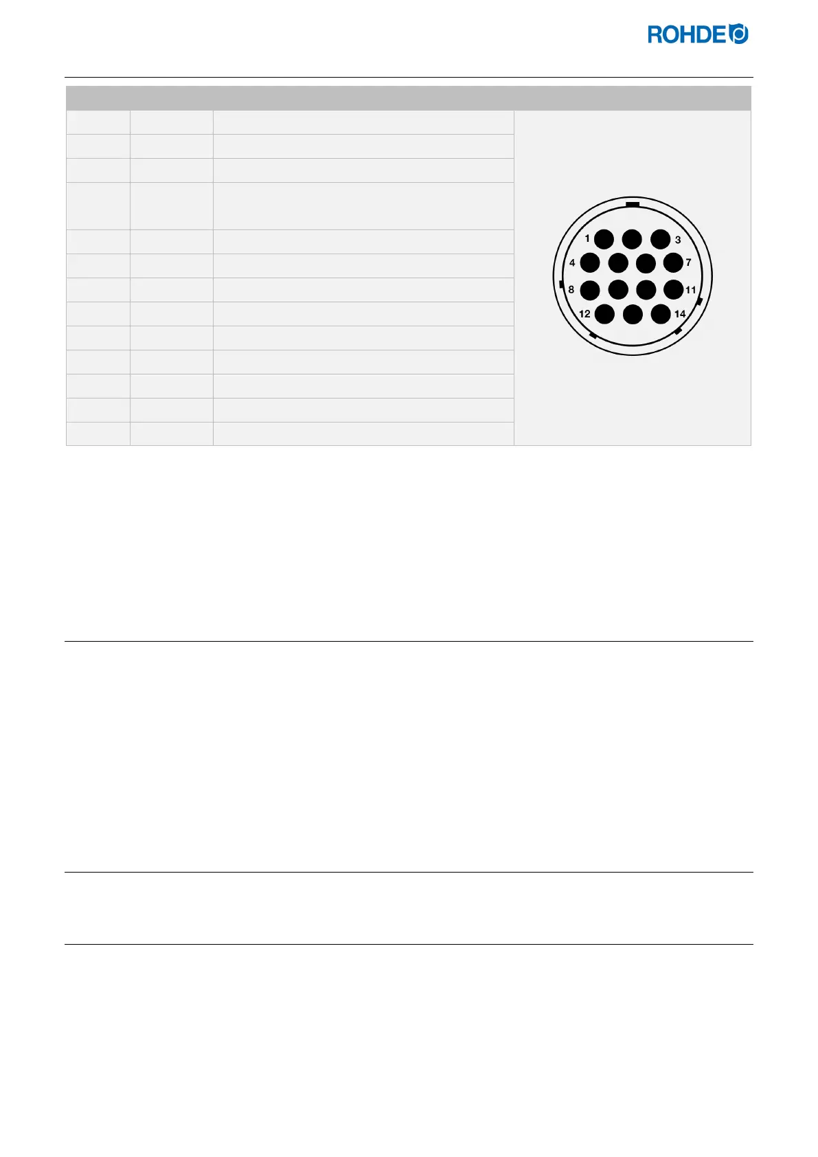
2.6. Plug pin assignment
Pin no. X = Used Description Plug pin assignment view
X Thermocouple 1 (Type S) +
X Thermocouple 1 (Type S) - --
− Not used
− Not used
− Not used
− Not used
− Not used
X L1 feed 230 V AC
X N feed
− Not used
− Not used
X Safety contactor switch output
X Neutral conductor switch output
X Zone 1 switch output
Note:
• Each switching output can switch a maximum of 250–300 mA at 230 V.
• It is essential to use a relay at these outputs to switch loads.
• The wiring of the mating CPC 14 socket can vary between kiln manufacturers! Non-observance can result
in damage to the controller and kiln.
2.7. Kiln contactor protective circuit
The coil of each kiln contactor should be suppressed with a varistor. The varistor must be connected directly across
the coil terminals on each contactor. ROHDE kilns are delivered this way as standard. For kilns from other
manufacturers, suitable products are available as accessories from contactor manufacturers.
Attention!
If the contactors are not suppressed by a varistor, the controller can be damaged.
3. Safety Information
3.1. General information
Adhere to all safety and warning instructions for the control unit and observe the operating instructions and the
information on the warning signs for the kiln to which the control unit is connected.
Keep the instruction manuals for the control system and the kiln so
• the manual is always accessible to anybody working on the kiln, and
• the manual is always near the kiln.

 Loading...