49 / 293 - EN -
2.4.2. Overview of the program sections
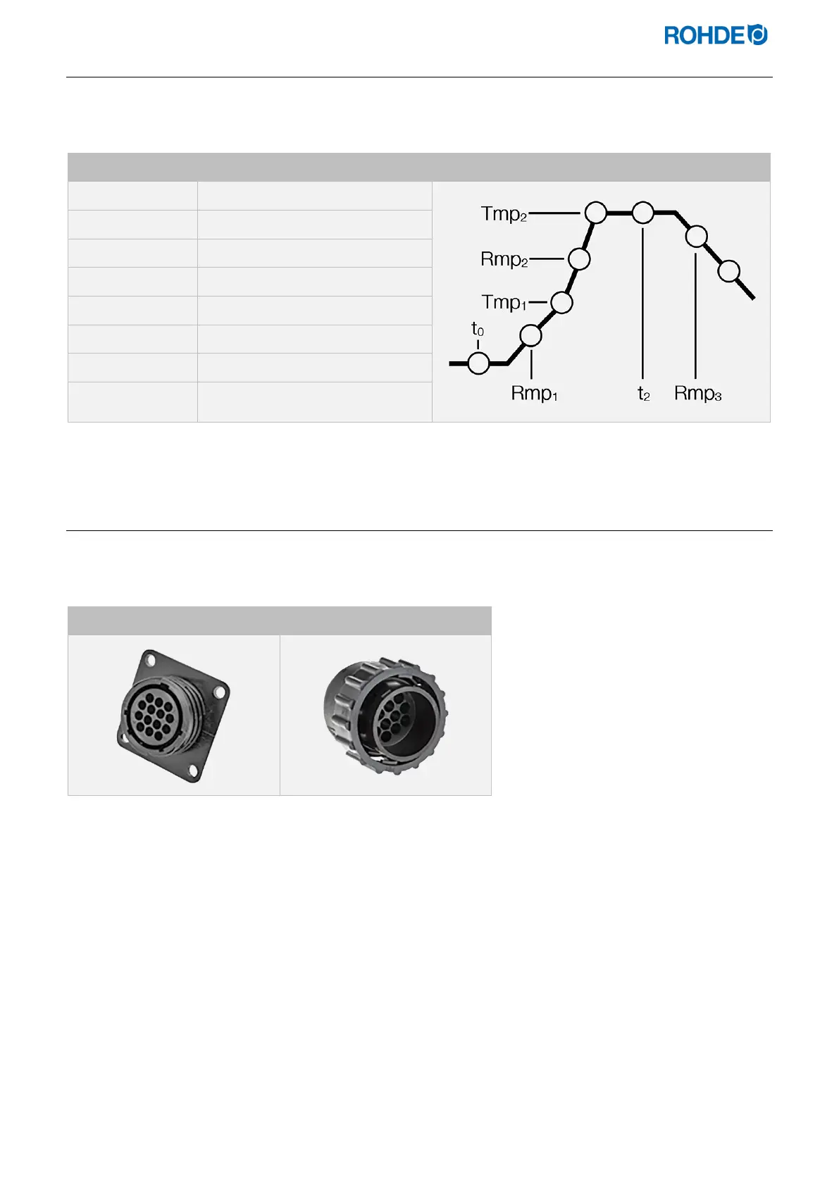
You will find a schematic firing curve on the front of the controller. It comprises different program sections. A flashing
LED indicator shows the program section you have entered.
Section Description Illustration
Program delay
1st heating rate
1st switch point
2nd heating rate
End temperature
Soak time at end temperature
Cooling rate
Indicates the end of the program
2.5. Connector features
The control unit is connected to the kiln via a 14-pin connector. The black 14-pin socket provided for this is located
on the switch cabinet of the kiln (near the electrical supply line).
CPC 14 kiln socket CPC 14 controller plug

 Loading...