Stripping the master cylinder
Referring to figure 15, remove the protective boot E, dislodge the circlip B and withdraw the rod D together with the
disc C.
Remove the piston together with the spacer, the seal, the backup washer and the spring beneath.
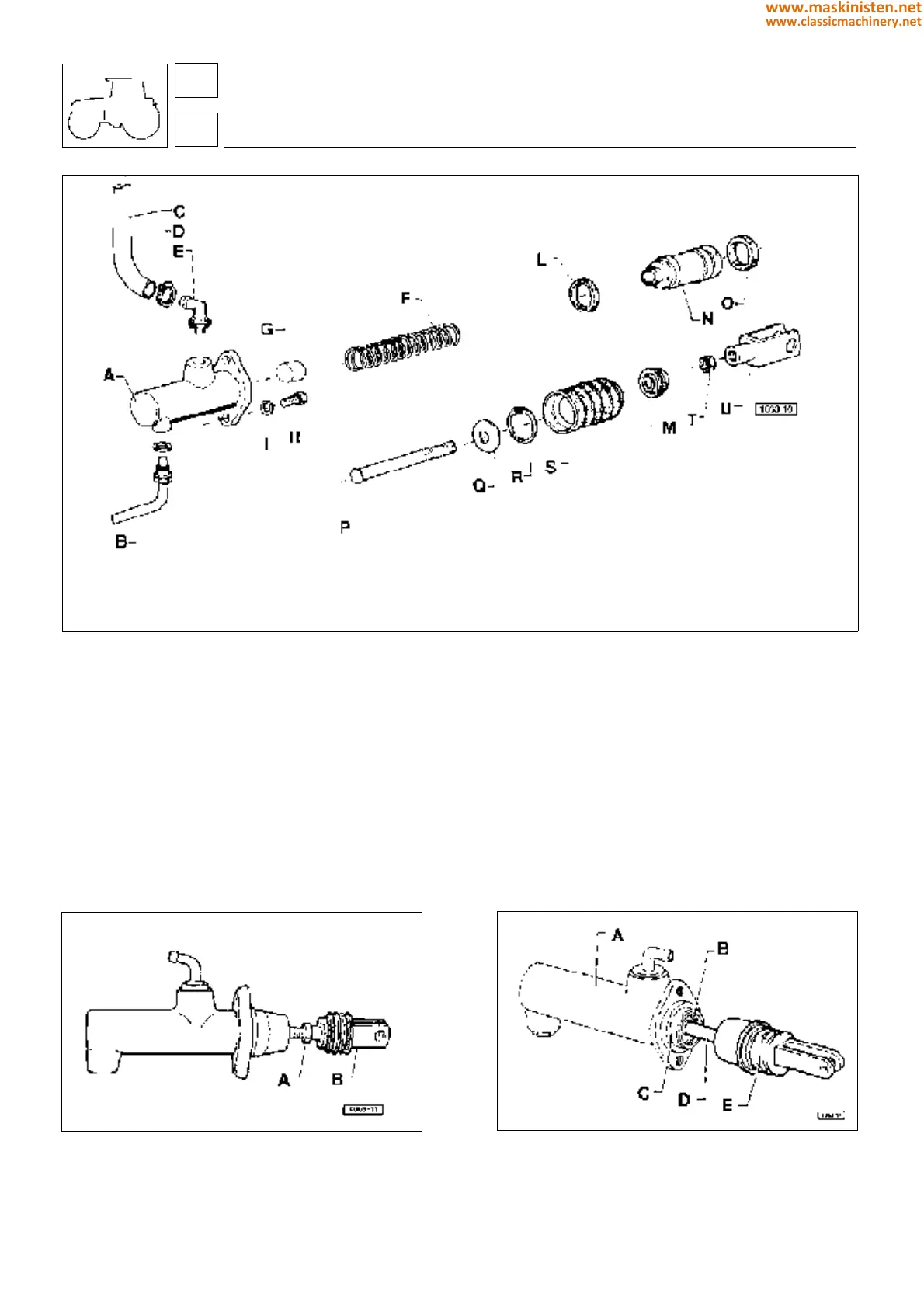
Fig. 14 - Clutch pump control positioning.
1 - Locknut
2 - Yoke
Fig. 13 - Clutch hydraulic pump parts.
clutch and transmission
clutch
A Hydraulic pump
B Delivery pipe union
C Delivery pipe
D Clamp
E Union
F Spring
G Spring holder
H Spring
I Shoulder ring
L Seal ring
M Spacer ring
N Piston
O Seal ring
P Rod
Q Support disk
R Snap ring
S Guard boot
T Nut
U Yoke
Fig. 15 - Pump control seal ring.
A - Pump
B - Snap ring
C - Support disk
D - Rod
E - Guard boot
23
2
116
www.maskinisten.net
www.classicmachinery.net