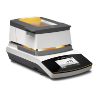
Communication Ports
The device offers four unique modes to
communicate to other Sartorius mois-
ture analyzers, a PC, with a network or
to the internal printer�
§ Serial – Transfer programs between
moisture analyzers (LMA1… [Mark 3] or
Mark 2) or interface with a PC
§ USB – For Sartorius Service only
§ Ethernet – connect to a network
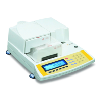
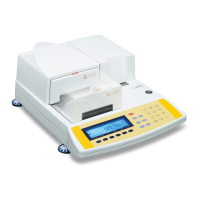
LMA100P:
§ Internal printer – permits result print-
outs at the analyzer
To set up serial communications to
match peripheral device:
§ From the Setup Menu screen, press the
6 key or highlight the Communication
Ports menu using the navigation keys
and press the Enter key�
§ Press the 1 key for Serial Port to display
the Serial Port menu screen�
§ Press the 1 key or On|Off soft key to
toggle the serial port On�
§ Press the 2 key for Select baud rate and
then the appropriate key to select either
300, 1200, 2400, 4800, 9600, 19200,
57600, or 115200� The screen will
return to the Serial Port menu screen�
§ Press the 3 key for Set up serial port to
make final selections:
– 8, no parity, 1 stop bit
– 7, even parity, 1 stop bit
– 7, odd parity, 1 stop bit
§ Finally, press the 4 key to toggle CTS
On or Off�
LMA100P:
To turn the internal printer Off, press
the 4 key from the Communication
Ports menu, or highlight Printer On and
toggle the On|Off soft key to display
Printer Off�
Note
To download or upload drying programs
from another Sartorius product (Mark 3,
Mark 2, Omni 1) refer to
operating instructions “Transfer
Programs” on page 61�
Serial Command Set
Through specific serial commands
entered via a personal computer inter-
faced to the device, all setup and opera-
tional functions of the analyzer can be
performed from the computer�
For a complete set of serial commands,
please contact Sartorius�
Pin Assignment Chart
Pin Configuration of 9 pin DE-9S
Pin Remark
1 Shorted with pins 4 and 6
2 TxD (out)
3 RxD (in)
4 Shorted with pins 1 and 6
5 GND
(tied to shell and digital ground)
6 Shorted with pins 1 and 4
7 CTS
8 RTS
9 No connection
53