34 VERSA SATEL
keypad: SERVICE MODE 2. HARDWARE 5. EOL 1 RESIST. / 6. EOL 2 RESIST.
You can define the resistor value for the expander zones when configuring the expander:
DLOADX program: “VERSA – Structure” window “Hardware” tab “Expansion modules”
branch [expander name],
keypad: S
ERVICE MODE 2. HARDWARE 1. KPDS & EXP. 2. SETTINGS [expander name].
The sum of values programmed for the resistors R1 and R2 may not be lower than
500
or higher than 15 k
.
You can program the value 0 for the resistor R2. In the 2EOL configuration you must
use then two resistors, the resistance value of each being equal to half the value
defined for the resistor R1.
In the EOL configuration, the resistance value is equal to the sum of values
programmed for the resistors R1 and R2.
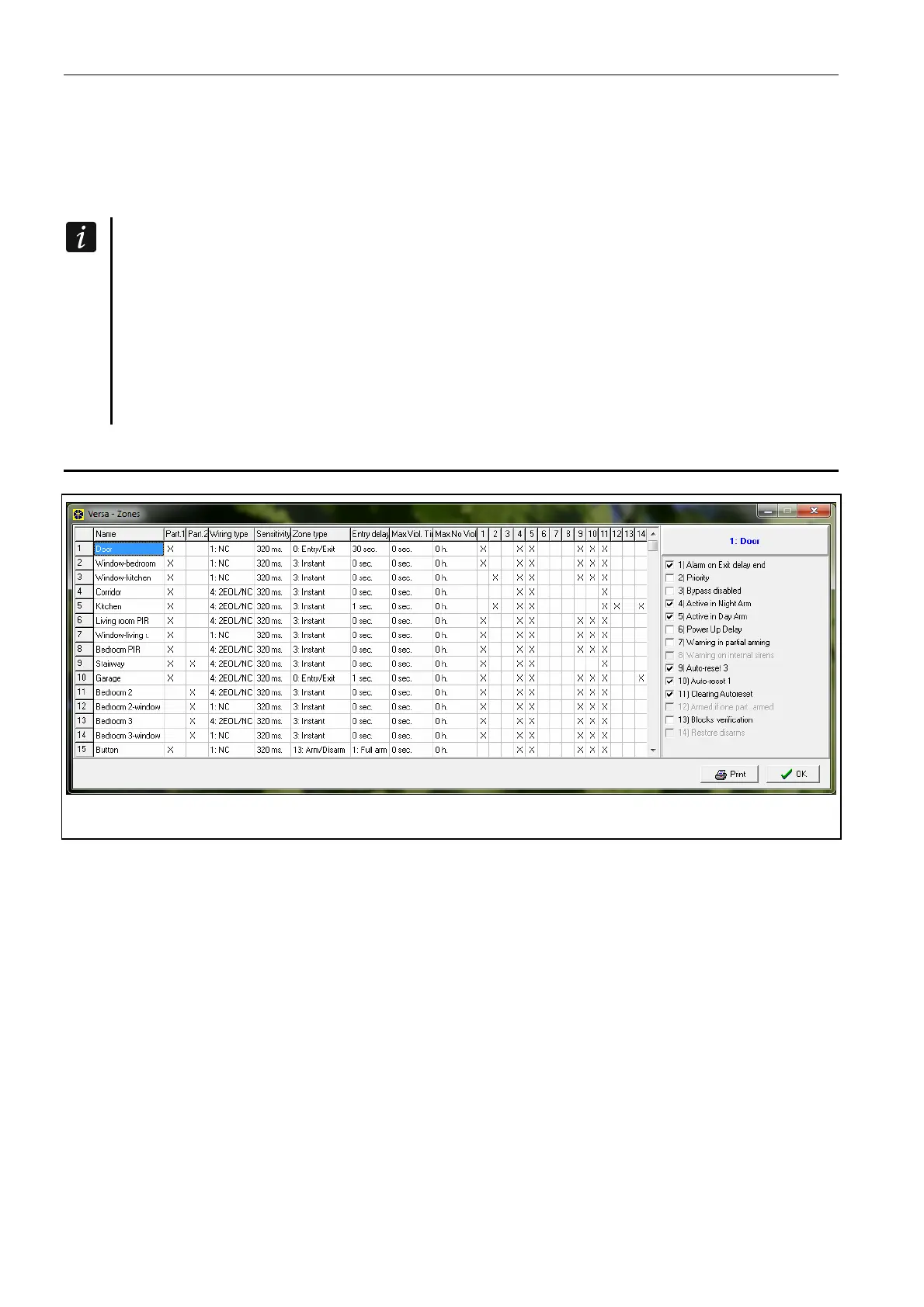
6.2 Configuring the zone parameters and options
Fig. 8. DLOADX program: “VERSA – Zones” window.
Parameters and options of the zones you can program:
DLOADX program:
– “VERSA – Structure” window “System” tab. Partition and zones are presented in the
tree-like form on the left-hand side of the window (Fig. 6). Click on the zone, the
parameters and options of which you want to configure.
–
“VERSA – Zones” window (Fig. 8).
keypad:
ZONES function (SERVICE MODE 2. HARDWARE 2. ZONES). The programming is
performed using the “step by step” method (see: p. 6):
1. Zone selection.
2. EOL type.
3. Sensitivity [wiring type NO, NC, EOL and 2EOL].
4. Pulse validity [only for ROLLER wiring type].
5. Pulses count [only for ROLLER wiring type].
6. Sensitivity [only for VIBRATION wiring type].
7. Pulses count [only for V
IBRATION wiring type].