Hardware Manual for the PCD2.M5 Series│Document 26/856; Version EN 12│2014-07-24
Saia-Burgess Controls AG
Analogue input modules
Input/output (I/O) modules
6-50
6
If an input receives a signal with incorrect polarity, the measurement results for the other
channelswillbesignicantlydistorted.
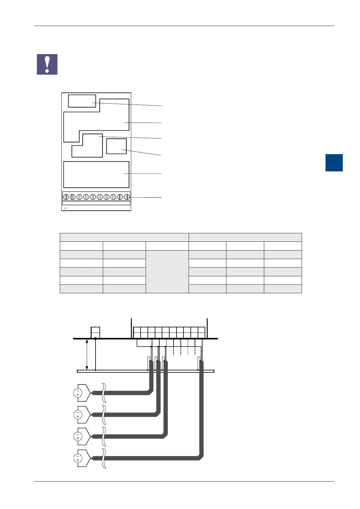
Connections
Bus connector
Bus interface
Reference voltage (and source)
A/D converter and multiplexer
Input filter
Screw terminals
9 8 7 6 5 4 3 2 1 0
E0123456E7
Digital/analogue values
Input signals and type Digital values
PCD2.W200 PCD2.W210 PCD2.W220 Classic xx7 Simatic
+ 10.0 V + 20 mA
Calculate the
appropriate
values with the
formulae at
the end of this
section
1023 1023 27648
+ 5.0 V + 10 mA 512 512 13824
+ 4 mA 205 205 5530
0 V 0 mA 0 0 0
– 10.0 V – 20 mA 0 0 0
Connection diagram for PCD2.W200
9 8 7 6 5 4 3 2 1 0
- E7 E6 E5 E4 E3 E2 E1 E0
-
PGND
PCD2/3.W200
Earthing bar
Shield
Signal
source
0…10 V
Signal
source
0…10 V
Signal
source
0…10 V
Signal
source
0…10 V
max. 25 cm
min. 2.5 mm2
Power PCD
Shield
Shield
Shield
 Loading...


