Saia-Burgess Controls AG
Hardware manual for PCD3 series │ Document 26-789 ENG19│ 2018-06-29
Power supply and connection plan
PCD3.Mxxx0 Classic CPU and expansion enclosure
3-27
3
100
Saia PCD3.C
200
Saia PCD3.C
200
Saia PCD3.C
W
8
0
0
W
8
0
0
W
8
0
0
W
8
0
0
W
8
0
0
W
8
0
0
W
8
0
0
W
8
0
0
A
8
6
6
A
8
6
6
A
8
6
6
A
8
6
6
6860
ETH 2.1 ETH 2.2
Ethernet 2
USB
Saia PCD3.M
100
Saia PCD3.C
100
Saia PCD3.C
A
8
6
6
A
8
6
6
A
8
6
6
A
8
6
6
A
8
1
0
A
8
1
0
A
8
1
0
A
8
1
0
A
8
1
0
A
8
1
0
A
8
1
0
A
8
1
0
Extension cable PCD3.K106
0
16
Slot 84
12
20
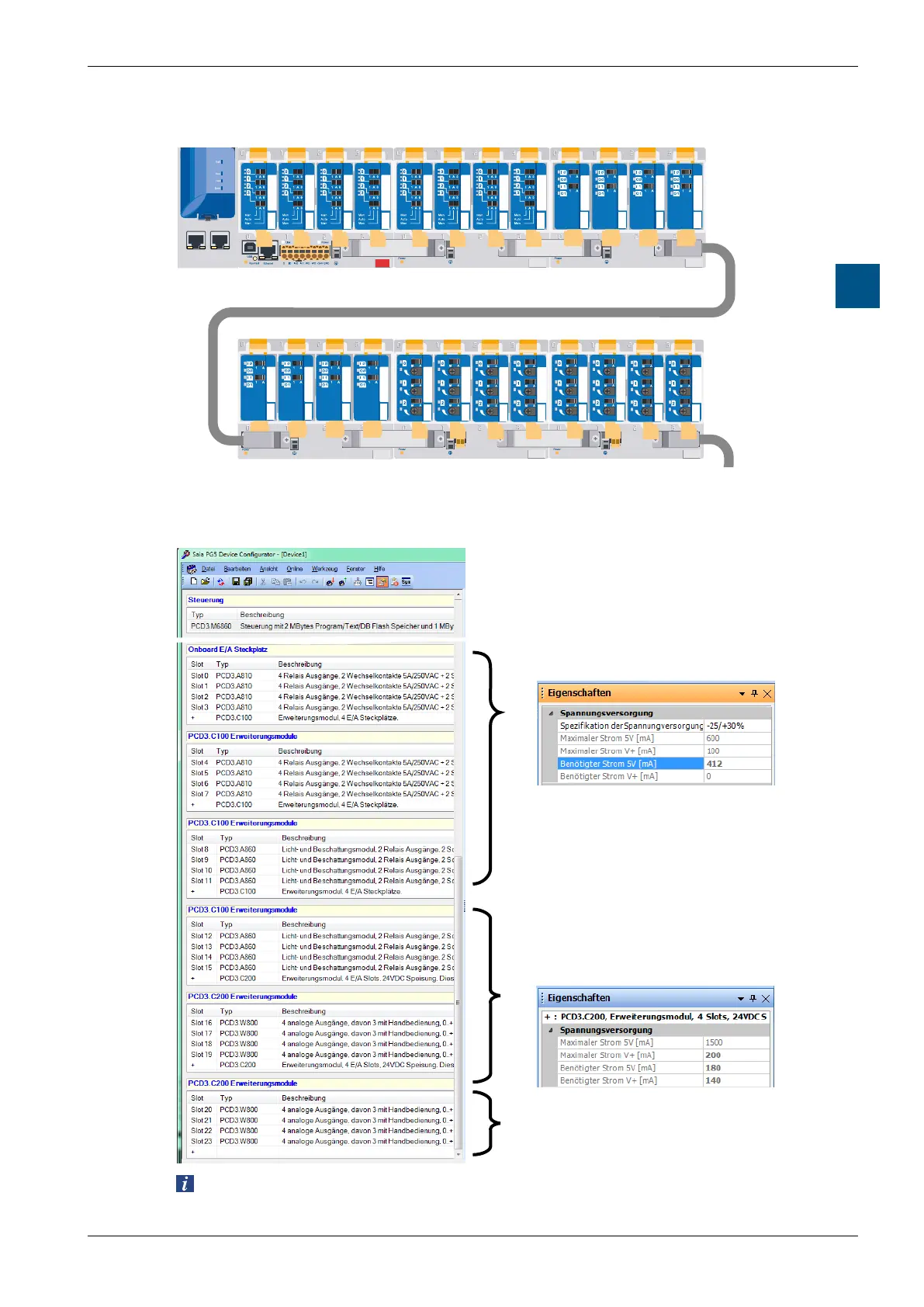
TheexampleshownabovelooksintheDeviceConguratorregardinginternal
power supply as follows:
The module carriers have 2 or 4 slots.
The last, empty line with only a +, indicates
that no further module carrier follows, i.e.,
the end of the system structure.
Total current of the I/O modules in the CPU and
all following in the PCD3.C100 or PCD3.C110
module carriers.
As soon as a PCD3.C200 module carrier with
power supply is used, the calculation starts
again until the next PCD3.C200 etc.
Once the current limit is exceeded, the
configurator will reports this.
TheDeviceConguratorshowsthepowercon-
sumption according to the modules used.
The CPU supplies slot 0 ... 11 (with two
PCD3.C100), i.e. a total of 12 I/O modules
with internal current of 412 mA [5V].
188 mA are reserve.
The last entry in the module carrier stands
for the following, in this case, a power-
supplying PCD3.C200 module carrier.
The configurator displays the power
consumption of the next I/O modules up to
another PCD3.C200.