Saia-Burgess Controls AG
Hardware manual for PCD3 series │ Document 26-789 ENG19│ 2018-06-29
Communication interfaces
5-8
Onboard interfaces
5
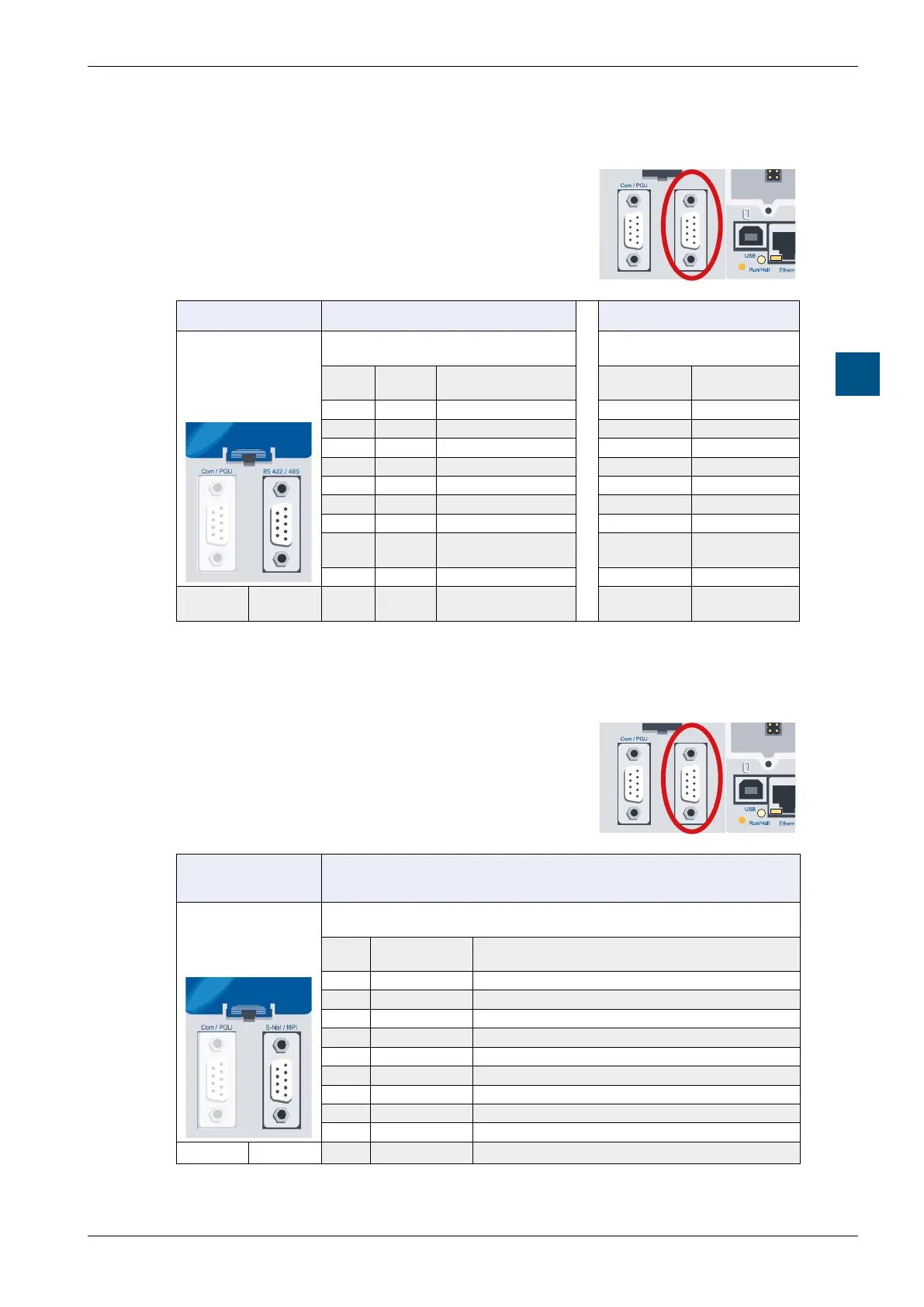
5.3.3 RS-485 / RS-422 (port 3)
This interface is routed to a 9-pin D-sub connector
(socket) and is of type RS-485 / RS-422.
S-Net / MPI
PCD3.M5340, PCD3.M5360 PCD3.M5xx0
5
4
3
2
1
9
8
7
6
10
11
RS-422
Port 3
RS-485
Port 3
D-Sub
pin
Signal Explanation Signal Explanation
1 /RXD Receive data - --- ---
2 /CTS Ready to send - --- ---
3 /TXD Send data + /RxD /TxD Receive/Send +
4 /RTS Send request - --- ---
5 PGND Data ground PGND Data ground
6 RXD Receive data + --- ---
7 CTS Ready to send + --- ---
8 TXD Send data - RxD TxD
Receive /
Send -
9 RTS Send request + --- ---
Port 0 Port 3 10/11
*)
PGND Shield dimensions PGND
Shield
dimensions
*)
*) Mounting screws of the D-Sub female connector housing
5.3.4 RS-485 / S-Net / MPI (port 10)
This interface is routed to a 9-pin D-sub connector
(female) and is of type RS-485.
S-Net / MPI
PCD3.M5xx0
(except PCD3.M5340 and PCD3.M5360)
5
4
3
2
1
9
8
7
6
10
11
Port 10
D-Sub
pin
Signal Explanation
1 GND GND
2 M24 0V of the 24V power supply
3 RxD/TxD-P
1)
Receive/Transmit data pos.
4 CNTR-P Control signal for repeaters (direction control)
5 DGND
1)
Data transmission potential (volume to 5V)
6 VP
2)
Supply voltage of the terminating resistors-P
7 P24 Output voltage plus 24V
8 RxD/TxD-N
1)
Receive/Transmit data neg.
9 n.c. ---
10/11
*)
PGND Shield dimensions
*)
Port 0 Port 10
*) Mounting screws of the D-Sub female connector housing
1)
Obligatory signals (it is imperative that the user makes this available)
2)
The signal is provided by the controller