Saia-Burgess Controls AG
Hardware manual for PCD3 series │ Document 26-789 ENG19│ 2018-06-29
Appendix
A
A-6
Denitionsfortheserialinterfaces
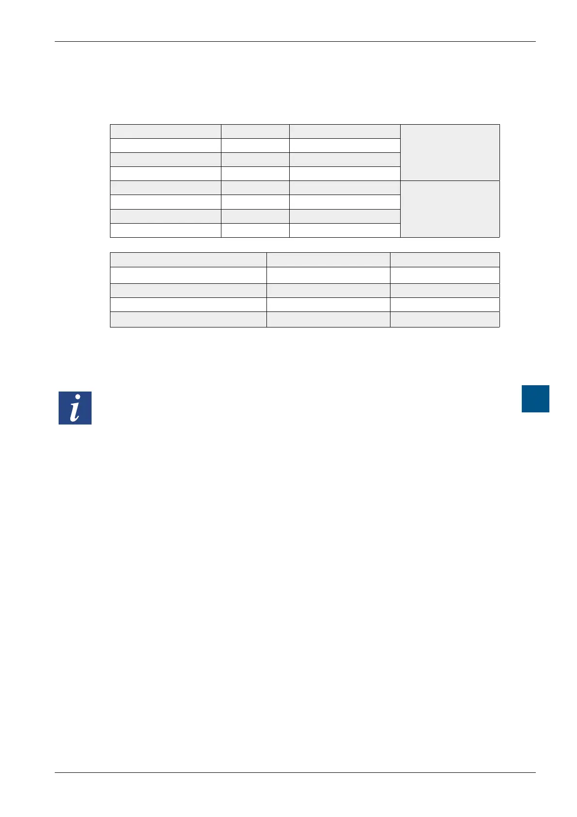
A.2.3 TTY/current loop
Signals to TTY/current loop
Connection 1 TS Transmitter source
Sender
Connection 3 TA Transmitter anode
Connection 6 TC Transmitter cathode
Connection 8 TG Transmitter ground
Connection 2 RS Receiver source
Receivers
Connection 4 RA Receiver anode
Connection 7 RC Receiver cathode
Connection 9 RG Receiver ground
Signal type Setpoint value Nominal value
Current for logical L (space) –20 mA to + 2 mA 0 mA
Current for logical H (mark) +12 mA to +24 mA +20 mA
No-load voltage on TS, RS +16 V to +24 V +24 V
Short circuit current on TS, RS +18 mA bis +29.6 mA +23.2 mA
The idle status for data signals is mark.
The operator uses wire bridges on the screw terminal blocks to select the
switching type active or passive.
The max. transmission rate for TTY/current loops at 20 mA is 9600 bit/s.