Saia-Burgess Controls AG
Hardware manual for PCD3 series │ Document 26-789 ENG19│ 2018-06-29
Appendix
A
A-3
Denitionsfortheserialinterfaces
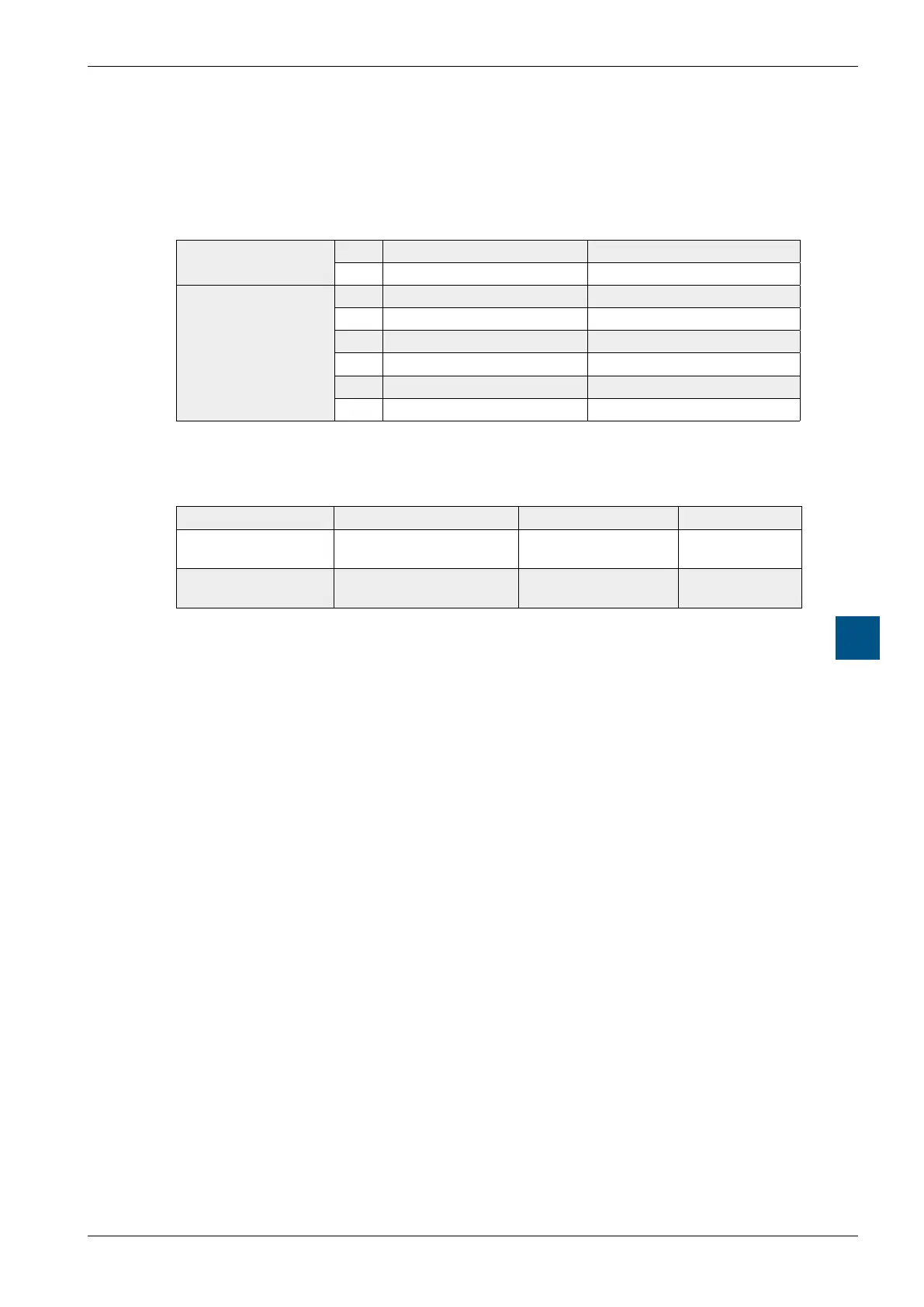
A.2.1 RS-232
Designation of the signal lines
Data lines
TXD Transmit data Send data
RXD Receive data Receive data
Signal and message
lines
RTS Request to send Activate transmitter
CTS Clear to send Ready to send
DTR Data terminal ready Terminal ready
DSR Data set ready Ready
RI Ring indicator Incoming call
DCD Data carrier detect Partner ready
Signals to RS-232
Signal type Logical status Setpoint value Nominal value
Data signal 0 (space)
1 (mark)
+3 V to +15 V
-15 V to -3 V
+7 V
-7 V
Control/
message signal
0(o)
1 (on)
-15 V to -3 V
+3 V to +15 V
-7 V
+7 V
The idle state of the - data signals = mark
-controlandmessagesignals=o