Saia-Burgess Controls AG
Hardware manual for PCD3 series │ Document 26-789 ENG19│ 2018-06-29
Communication interfaces
5-6
Onboard interfaces
5
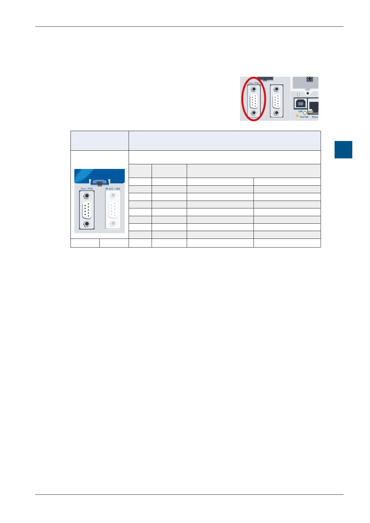
5.3.2 RS-232 connector (port 0) as communication interface and
as programmer connection (only PCD3.M5xx0 / M6xx0)
This interface is routed to a 9-pin D-sub connector
(female) and is of type RS-232.
S-Net / MPI
PCD3.M5xx0
PCD3.M6xx0
5
4
3
2
1
9
8
7
6
RS-232
Port 0
D-Sub
pin
Signal Meaning
1 DCD Data carrier detect Data carrier detected
2 RXD Receive data Receive data
3 TXD Transmit data Send data
4 DTR Data terminal ready Terminal ready
5 GND Signal ground Signal ground
6 DSR PGU Connected PGU detection
7 RTS Request to send Start up transmitter
8 CTS Clear to send Ready to send
9 n.c. not connected ---
Port 0 Port 10
1)
Obligatory signals (it is imperative that the user makes this available)
2)
The signal is provided by the controller
The interface can be used for the following purposes:
(see next page)