Saia-Burgess Controls AG
Hardware manual for PCD3 series │ Document 26-789 ENG19│ 2018-06-29
PCD3 CPUs
PCD3.Mxxx0 Classic CPU and expansion enclosure
3-7
3
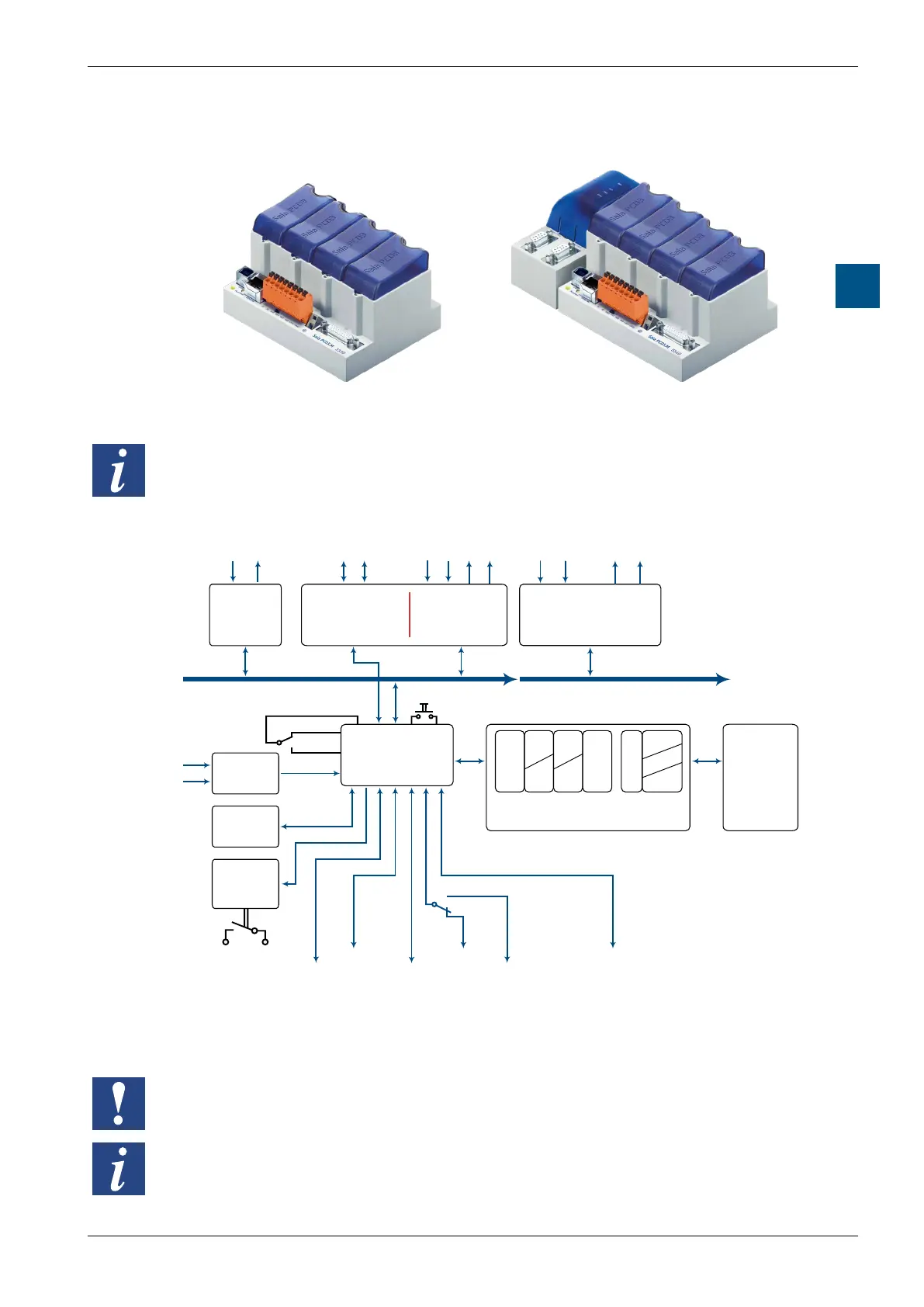
3.4 PCD3 CPU
PCD3.M3xxx PCD3.M5xxx and PCD3.M6xxx
The redundant CPU PCD3.M6880 and the matching smart RIO PCD3.T668 are
described in the manual 27-645 Standby Controllers.
3.4.1 Block diagram PCD3.Mxxx0
M
E
M
A
E
E
P
R
O
M
DB
TX
P
T
vol
R
F
vol
M
O
R
Y
P
C
nvol
nvol
F
nvol
S-Net/
MPI
RS-485 COM/PGU
Ethernet
TCP/IP
Feed
I/O in base device
Slots 0…3
Addresses 0…63
I/O in extensions
PCD3.C100/.C110/.C200
Addresses 64…1023
F1xx + F2xx Module
Slots 0…3
Serial data interfaces
Fieldbus switching
CPU
E/A-Bus
Backup
User
memory
USER MEMORY
E/A-Bus
USER MEMORY
Register
Timer
(Counter)
(Flag)
(volatile)
non volatile
Programs
Texts
Data blocks
R
T
C
F
vol
nvol
P
TX
DB
Modem RS-232
“Full Handshaking”
Interrupt
inputs
Date-Time
nvol
Watch-Dog
USB connection for the
programming device
E/A-Bus
STOP
RUN
1)
2)
3)3) 3)
4)
1) Connection for the programming unit
2) except PCD3.M3020/3120
3) only PCD3.M5xx0/PCD3.M6xx0
4) with PCD3.M3330 or PCD3.M5540
I/O modules and I/O terminal blocks may only be pulled out or inserted when the
Saia PCD
®
is in a de-energised state. The external +24 V power supply of the
modulesmustalsobeswitchedo.
To avoid data loss, a battery change must be carried out with the power switched on.