Saia-Burgess Controls AG
Hardware manual for PCD3 series │ Document 26-789 ENG19│ 2018-06-29
Communication interfaces
5-12
USB PGU interface for programming device connection
5
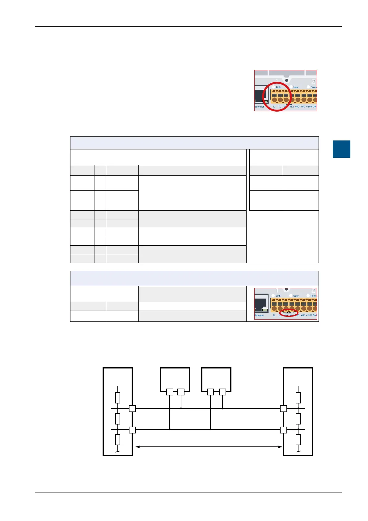
On the same terminal block for power supply, the port
2 interface with two terminal connections (D and /D) is
arranged on the left side of the plug.
For all CPU types
Terminal block (item no. 440549950) for power supply, watchdog,
interrupt inputs and port 2
Probus
Cabel Pin Signal Explanation Signal Wiring
Rx - Tx 1 D
Port 2
RS-485 to 115.2 kbit/s as a free user
interface or Profi S-bus up to 187.5kbits/s
(except PCD3.M5440 and PCD3.M5540)
RxD/TxD-N
A
green
/Rx - /Tx 2 /D RxD/TxD-P
B
red
3 Int0
2 interrupt inputs 24VDC or 1 quick
counter 24 VDC
4 Int1
5 WD
Watchdog / closed relay contact
6 WD
7 +24V
Power supply
8 GND
RS-485 terminating resistors
Switch
position
Description Explanation
left O without terminators
right C with terminators
Example of a RS-485 network setup with terminating resistors:
+5 V
/RX - /TX
n n
29 n
/n
/n/n
28
RX - TX
+5 V
Pull up
330 Ohm
Abschluss
Widerstand
150 Ohm
Segmentlänge max. 1200 m
max. 32 Stationen
Bus RS-485
Anfangsstation Zwischenstationen Endstation
Pull down
330 Ohm