Saia-Burgess Controls AG
Hardware manual for PCD3 series │ Document 26-789 ENG19│ 2018-06-29
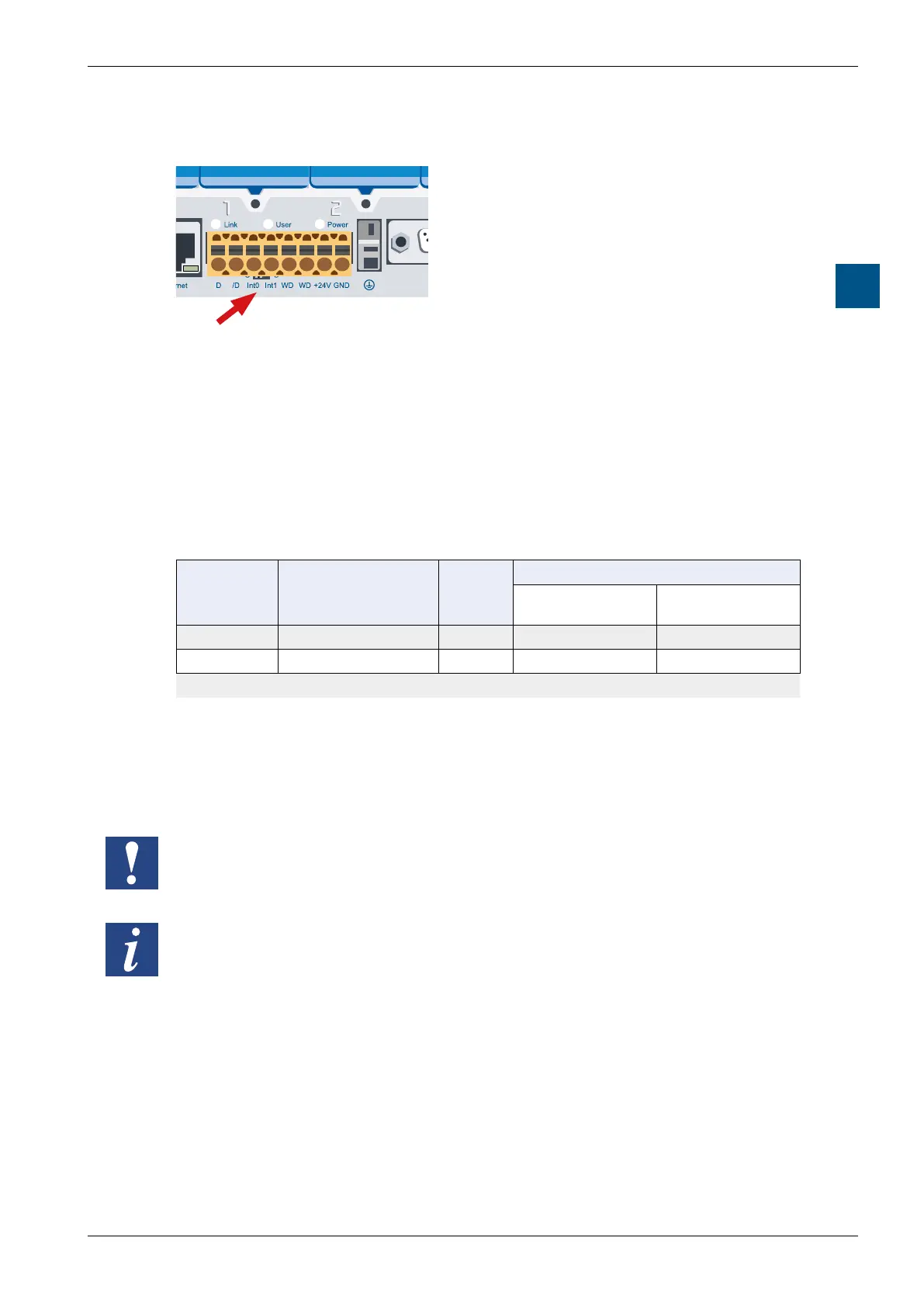
Connections on orange terminal block
PCD3.Mxxx0 Classic CPU and expansion enclosure
3-39
3
3.15.2 Interrupt inputs
5540
Saia PCD3.M
Saia PCD3Saia PCD3
Saia PCD3Saia PCD3
Saia PCD3Saia PCD3
Saia PCD3Saia PCD3
Terminal 3 and 4 for interrupts inputs Int0 and Int1
Basics
The digital input modules are not suitable for immediate reaction to events or fast
countingbecauseoftheinputltersandtheinuenceofthecycletimeoftheuser
program. Most CPUs have 24 VDC interrupt inputs for this purpose.
Two interrupt inputs are located on the main PCB and can be connected via the
8-pin, pluggable terminal block (terminals 3 and 4). Source operation is used.
Interrupt
inputs
Called XOB on
positive edge
Plug
terminal
Direct input query
Base and
standard CPU
Power CPU
PCD3.Mxx60
INT0 XOB 20 3 I 8100 ---*
INT1 XOB 21 4 I 8101 ---*
*availableviamediamappinginthedevicecongurator
An associated XOB is called (e.g. XOB 20) on a positive edge on the interrupt
input. The code in this XOB determines how the event responds, e.g. by
incrementing a counter.
The code in XOBs, which are called by interrupt inputs, must be kept as short as
possiblesothatsucienttimeremainsbetweentheinterruptstoprocesstherest
of the user program.
Many FBoxes are intended for cyclic calling and are therefore not or only partially
suitable for use in XOBs.
Exception: The FBoxes of the Graftec family (standard library) are well suited.
 Loading...


