Saia-Burgess Controls AG
Hardware manual for PCD3 series │ Document 26-789 ENG19│ 2018-06-29
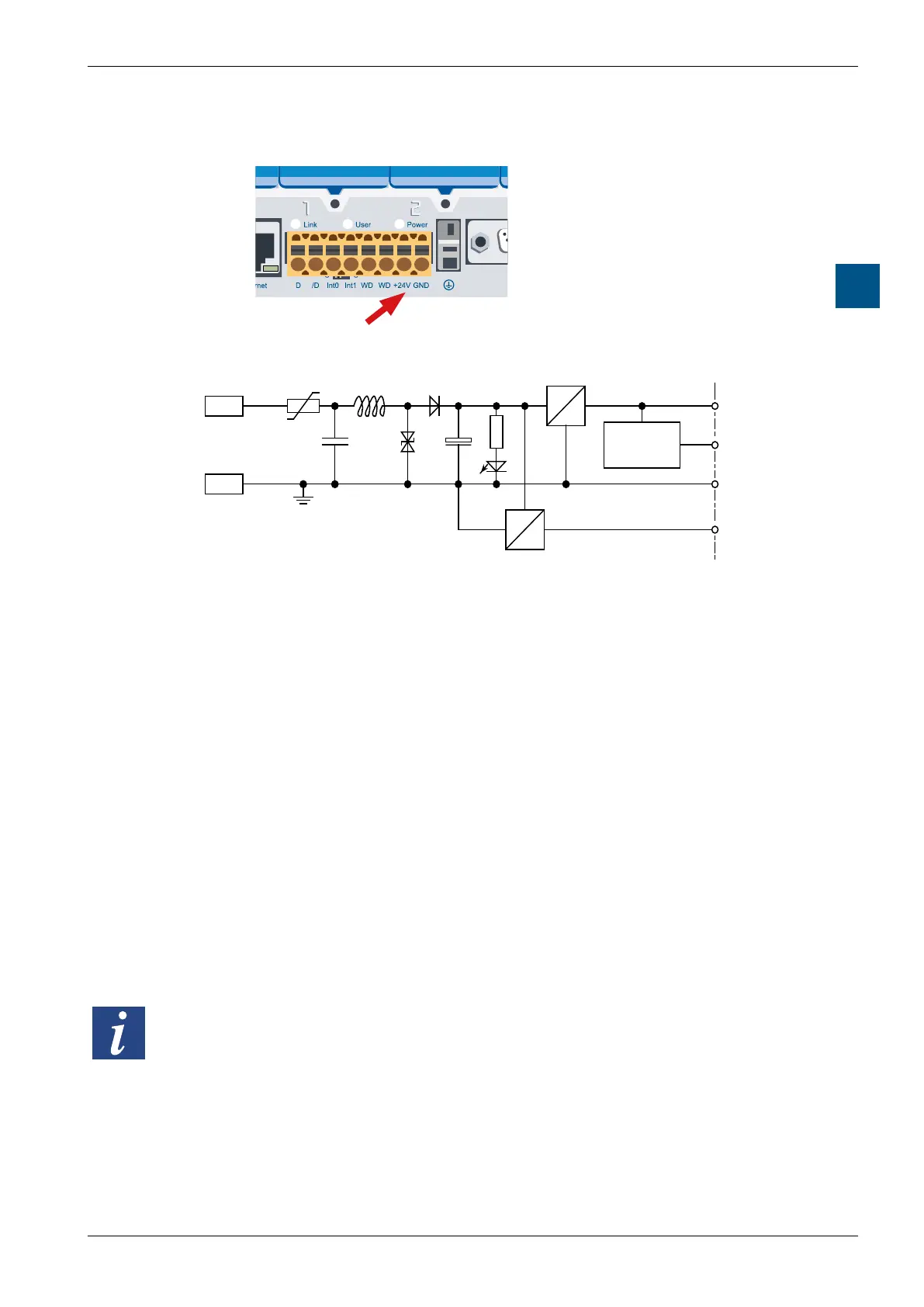
Power supply and connection plan
PCD3.Mxxx0 Classic CPU and expansion enclosure
3-26
3
3.9.2 Internal power supply
5540
Saia PCD3.M
Saia PCD3Saia PCD3
Saia PCD3Saia PCD3
Saia PCD3Saia PCD3
Saia PCD3Saia PCD3
Terminals for power supply 24 VDC
GND
+5V
CLR
0V
+V
(16...24V)
LED
24V
39V
PTC
PCD3
+24 V
Voltage-
monitor
5V
PCD-Bus
Supply 24 VDC
DC
DC
DC
DC
Resilience of the internal power supply
+5 V 600 mA
+V (16…24V) 100mA(theDeviceConguratorincludedinthePG5helpsto
determine the exact possible current loads).
3.9.3 Internal power supply for more than one module carrier
The power supplies of the CPU and RIOs are intended for internal electronics. The
internal power supply of the I/O plug-in modules does not apply to the assignment
and supply of the outputs of any kind. These must be supplied per I/O module at
the terminal block.
As soon as the number of inputs / outputs exceeds the four module slots per
CPU or RIO, the additional power requirement for the planned expansion must be
calculated for expansion with module carriers.
ThePG5DeviceConguratorhelpstocalculatehowmanyPCD3.C200module
carriers should be used per system.
ThePCD3.C200modulecarriershaveapowersupplythatisgenerallysucient
for its plug-in modules and 1 to 2 module carriers, depending on which I/O
plug-in modules are used. If the system structure increases again, additional
PCD3.C200s need to be deplayed.
Generally, 1 to 2 module carriers of type PCD3.C100 and/or PCD3C110 can be
supplied with power per PCD3.Mxxx, RIO PCD3.T6xx and PCD3.C200 CPU,
depending on the I/O module types used.