Saia-Burgess Controls AG
Hardware manual for PCD3 series │ Document 26-789 ENG19│ 2018-06-29
Data retention in the event of power failure
PCD3.Mxxx0 Classic CPU and expansion enclosure
3-30
3
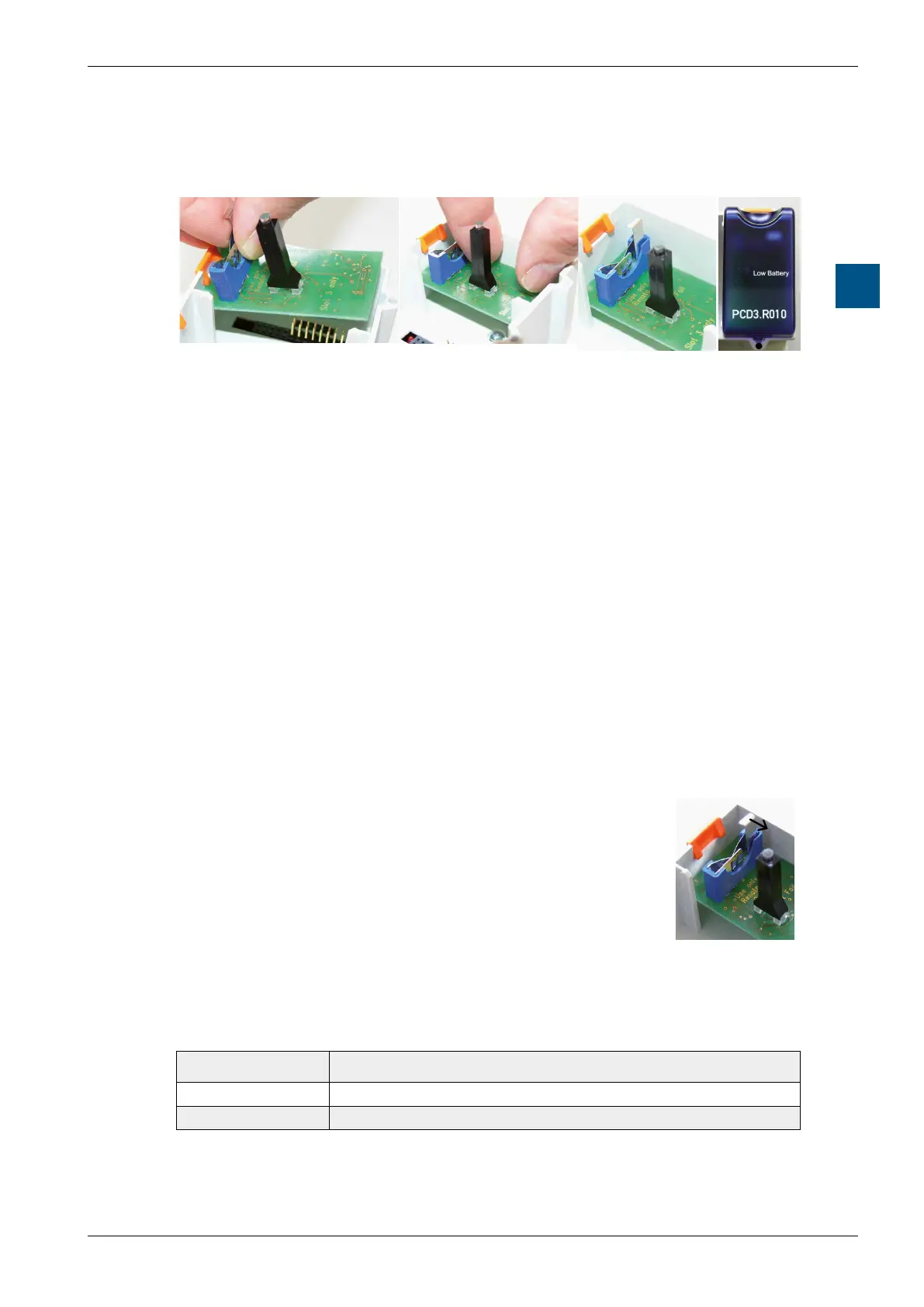
Installation rules:
1. PlacePCBoverslot#3(batteryholderup)
2. Insert PCB horizontally. Make sure that the connector pins are inserted
correctly into the corresponding connector of the slot
3. Press PCB all the way to the stop (1 cm distance between the PCB and the
base of the grey Saia PCD
®
housing)
4. InsertthebatteryandplacethebatteryI/Ocoveronslot#3.
Battery monitoring:
A red LED light on the module indicates a low battery that needs replacing. It still
has a residual capacity, but only for a few days. A low battery also creates an entry
in the history list and calls the XOB 2 (if programmed).
IfthebaseaddressofthePCD3.R010isread(=48forslot#3),thebatterystatus
is read out:
0 for low battery (or module error or module not present ...)
1 for battery OK
Insert or replace the battery:
The battery change (not module change) takes place while
under voltage
1)
(XOB2 is called)
● Pull the lock clip slightly in the direction of the arrow
● Remove the battery
● Insert the CR 2032 Renata button cell so that the positive
pole makes contact with the locking clip
1) Replacing the battery with the Saia PCD
®
odoesnotresultinprogram/datalossaslongastheSaiaPCD
®
Supercap has not been depleted.
Ordering information:
Type Description
PCD3.R010 Battery module for PCD3.M3xxx
4 507 4817 0 Battery type CR 2032 Renata lithium, shelf life 1-3 years
2)
2
) Dependingontheambienttemperature,thehigherthetemperature,theshorterthebueringtime