Page 7 of 86 SCHÄFER IT-Systems
Industriestraße 41 D-57518 Betzdorf
Phone: +49 (0) 2741/283-770 sales@schaefer-it-systems.de www.schaefer-it-systems.de As
amended on 16/8/2019 (subject to technical changes)
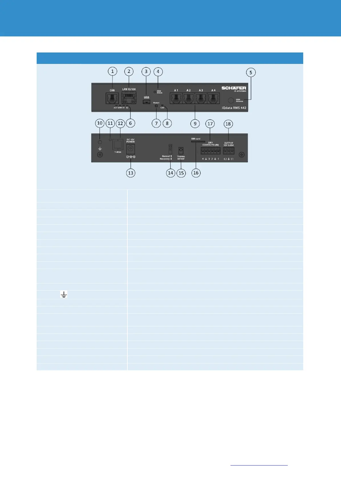
Digital contact RJ12 for connection of CAN sensors and CAN extensions
on a CAN bus with auto-sensing
Ethernet 10/100 Base-T-Port
to connect a USB camera or reset the device
displays the GSM SIM card status. Flashing = Status ok (OPTIONAL)
Contact for GSM antenna in case of integrated GSM modem (OPTIONAL)
indicates the device status, E1, E2 signal 12V relay status
Configuration in progress
“CAN” lights up
permanently
8x RJ12 analogue & digital sensor inputs with auto-sensing
external earthing M4 internal thread
to activate the 1-WIRE bus internal switch to "ON".
1-WIRE module is switched on
serial communication protocol, for communication via data line plus
ground reference between Master (RMS 442+) and 1-Wire Slave device
Power supply DC 12V 2A via power supply unit
“Normal” ↑ Off = normal status / “Recovery” ↓ On = factory setting
Internal temperature sensor ± 1.0°C
SIM card slot with ejector for GSM modem (OPTIONAL)
2x 12VDC max 0.25A Alarm outputs