Page 8 of 86 SCHÄFER IT-Systems
Industriestraße 41 D-57518 Betzdorf
Phone: +49 (0) 2741/283-770 sales@schaefer-it-systems.de www.schaefer-it-systems.de As
amended on 16/8/2019 (subject to technical changes)
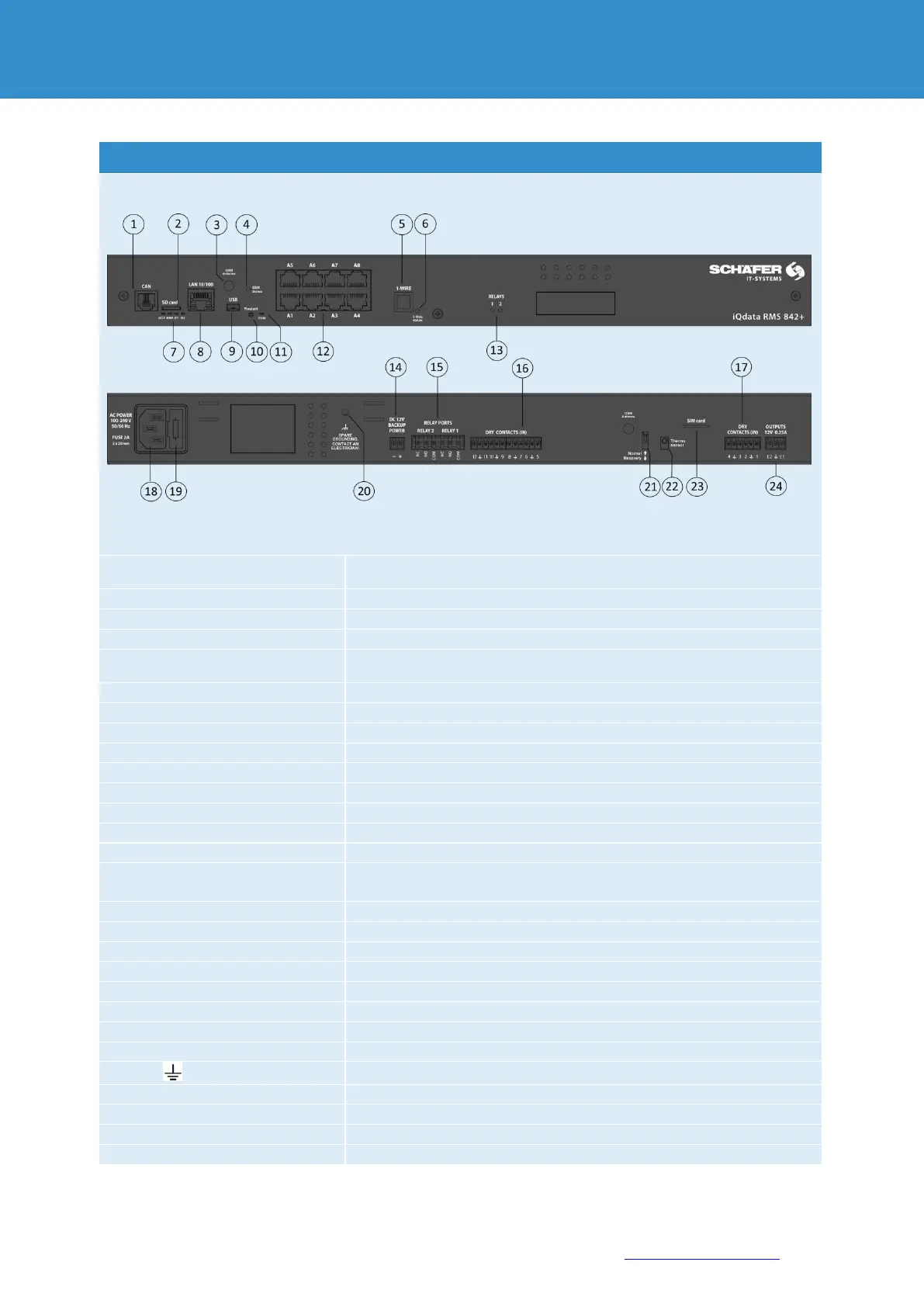
Digital contact RJ12 for connection of CAN sensors and CAN extensions
on a CAN bus with auto-sensing
SD, MicroSD card slot with ejector, for data storage
Contact for GSM antenna in case of integrated GSM modem (OPTIONAL)
displays the GSM SIM card status. Flashing = Status ok (OPTIONAL)
serial communication protocol, for communication via data line plus
ground reference between Master (RMS 842+) and 1-Wire Slave device
to activate the 1-WIRE bus internal switch to "ON".
1-WIRE module is switched on
indicates the device status, E1, E2 signal 12V relay status
Ethernet 10/100 Base-T-Port
to connect a USB camera or reset the device
Configuration in progress
“CAN” lights up
permanently
8x RJ12 analogue & digital sensor inputs with auto-sensing
Additional voltage output
16. “DRY CONTACTS 5...12”
Power supply 100-240V 50/60Hz IEC C14
external earthing M4 internal thread
“Normal” ↑ Off = normal status / “Recovery” ↓ On = factory setting
Internal temperature sensor ± 1.0°C
SIM card slot with ejector for GSM modem (OPTIONAL)
2x 12VDC max 0.25A Alarm outputs


 To Next Page