Hardware and technical data
INTECONT® Tersus Belt weigher, Instruction Manual
Schenck Process Group
BV-H2464GB, 1234
- 129 -
Isolation: Optocoupler
Power supply: +5 VDC internal
Current supply: max. 310 mA
Connector to bus activation: XP1: D-Sub 9-pole
XP3: Terminal 5-pole
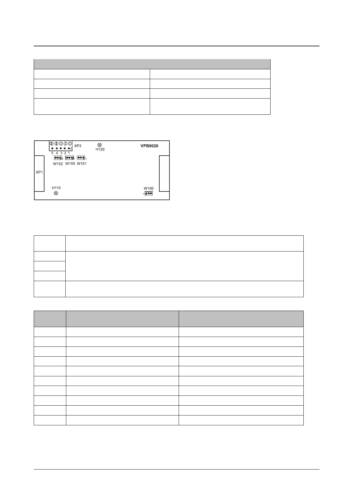
Arrangement of the components
Fig. 17: VPB8020 PROFIBUS module layout
Settings
W100 Determining the power supply:
The platform W100 always remains in position 2-3
W150 Bus termination:
The bus termination resistances must be activated at the first and last station of the bus. This is
done by setting all three jumpers on the board (W150, W151, W152) to position 1-2. By default the
resistances are not activated (position 2-3).
W151
W152
Bus address:
The addresses are set using parameters.
Signal
Signal
1 - B, RxD/TxD-P
*)
2 - A, RxD/TxD-N
**)
3 B, RxD/TxD-P
*)
DGND (0 V)
***)
4 CNTR-P (Control-P) VP (+5 V)
***)
5 DGND (0 V)
***)
SHIELD
6 VP (+5 V)
***)
-
7 - -
8 A, RxD/TxD-N
**)
-
9 - -
Housing SHIELD -
Tab. 5 : 'Bus activation' connector
 Loading...