General Diagram
INTECONT® Tersus Belt weigher, Instruction Manual
Schenck Process Group
BV-H2464GB, 1234
- 9 -
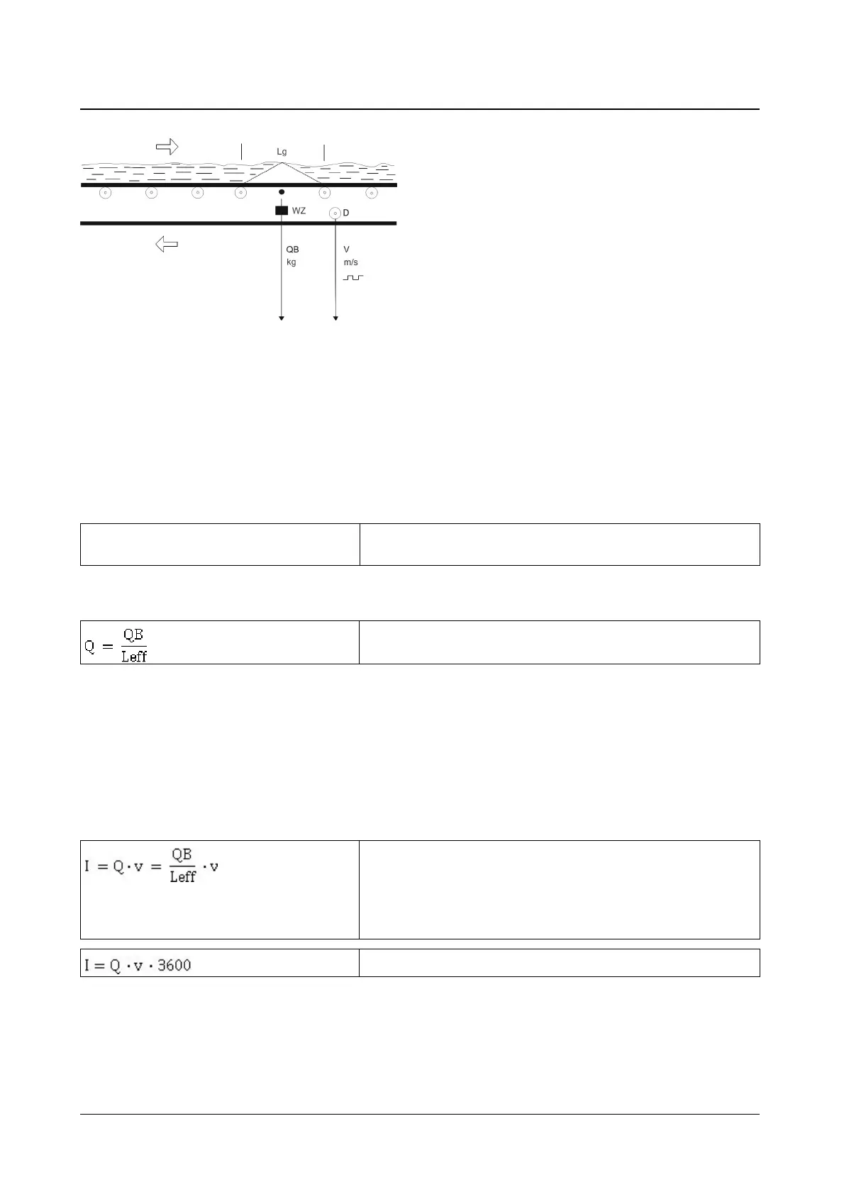
Fig. 2: The belt load of the weighbridge is not legal for trade
The material is transported over a weighing platform located beneath the belt, limited by 2 carrying idlers.
The load on the platform exerts a force on the load cell LC through one or more weighing idlers. The mea-
suring displacement is approximately 0.2 mm. The measuring rolls are linked with the frame construction via
parallel plate springs. The load cell output voltage is proportional to the platform load. It is recorded with a
suitable measuring amplifier.
The load distribution on a single-roll weighbridge is shown by the white triangle. Only half of the force from
the weight of the material is passed into the measuring idler. The following conversion formula applies to the
effective bridge length with single-roll weighbridges:
Leff = Lg / 2 Leff = effective weighing platform length
Lg = total weighing platform length
Weighing platforms with more than one weighing idler will have a different factor than 1/2.
Therefore the belt load in kg/m totals:
QB = total load on the weighbridge.
Belt speed
Belt speedBelt speed
Belt speed
The belt speed is recorded using velocity sensor D and converted into a corresponding pulse frequency.
Feed rate
Feed rate Feed rate
Feed rate
The readings Q and v are standardized in the unit to the physical quantities kg/m and m/s and multiplied
with one another. The product is feed rate I.
I in kg/s
Q in kg/m
v in m/s
QB in kg
Leff in m
I in kg/h
3.4
3.43.4
3.4
Characteristics
CharacteristicsCharacteristics
Characteristics
 Loading...