Schunk Bahn- und Industrietechnik GmbH
Adjustment Procedures
Procedure:
1. Assure pantograph is in resting position.
2. Loosen check nuts (2) at base frame and at upper frame.
3. Adjustment is done by turning the coupling rod tube (1):
Perform adjustment in ¼-turnings.
Turning CLOCKWISE
(SHORTEN coupling rod)
= Static contact force increases in the lower
working height / friction decreases
Turning COUNTER-
CLOCKWISE
(LENGTHEN coupling rod)
= Static contact force decreases in the lower
working height / friction increases
4. Checkup:
The upper frame has to rest on the Limit stops.
6. Fix check nuts (2).
5. Check trend of static contact force.
6. Check resting position ( Chapter #14.3).
7. Repeat adjustment if necessary.
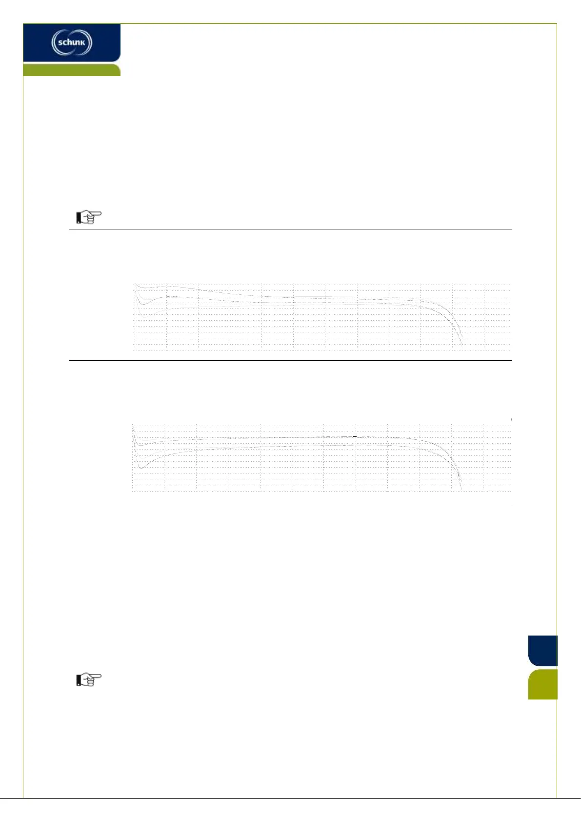
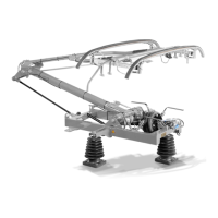
By changing the length of the coupling rod, geometry of the
pantograph has been modified.
Check trend of static contact force ( Chapter #14.10).
Adjust static contact force, if necessary ( Chapter #14.9).
0
250 750
1000
1250
1500
1750
2000
2250
2500
2750
3000
140
130
120
110
100
90
80
70
60
50
40
30
500
SB-025440_RS.dwg - Blatt 2
0
250 750
1000
1250
1500
1750
2000
2250
2500
2750
3000
140
130
120
110
100
90
80
70
60
50
40
30
500
SB-025440_RS.dwg - Blatt 3


 To Next Page