Schunk Bahn- und Industrietechnik GmbH
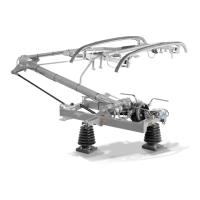
Adjustment Procedures
Procedure:
1. Loosen screw connection (3) of cam (4).
2. Loosen check nut (2).
3. Screw – out hexagon socket set screw (5) until it does NOT touch the screw
set (3) any more.
4. Adjustment is done by turning the adjustment screw (1) of the cam (4):
= Static contact force increases in the lower part of working
height.
Turning COUNTER-
CLOCKWISE
= Static contact force decreases in the lower part of working
height.
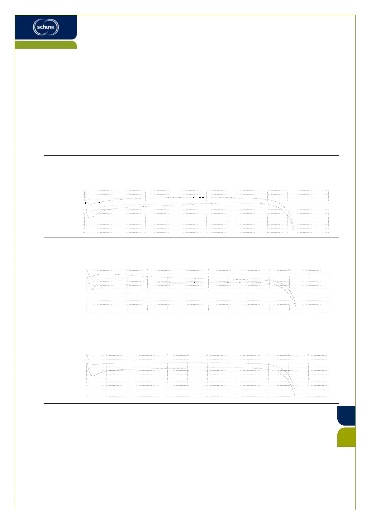
Adjust until the trend of static contact force is almost constantly over the whole working range:
5. Check static contact force with a spring scale or the Schunk KM11 device
( Chapter #14.8).
6. Screw – in hexagon socket set screw (5) until it touches screw set (3).
7. Fix check nut (2).
0
250 750
1000
1250
1500
1750
2000
2250
2500
2750
3000
140
130
120
110
100
90
80
70
60
50
40
30
500
SB-025440_RS.dwg - Blatt 5
0
250 750
1000
1250
1500
1750
2000
2250
2500
2750
3000
140
130
120
110
100
90
80
70
60
50
40
30
500
SB-025440_RS.dwg - Blatt 4
0
250 750
1000
1250
1500
1750
2000
2250
2500
2750
3000
140
130
120
110
100
90
80
70
60
50
40
30
500
SB-025440_RS.dwg - Blatt 1
 Loading...