MX-2300/2700 N/G SIMULATION 7 – 101
6) Sampling status check (3) (KCMY)
Press [K][C][M][Y] button to display the initial screen (K/C/M/
Y).
Press [NEXT] button to display the next category.
Press [BACK] button to display the previous category.
7) Sampling status check (4) (KCMY)
Press [K][C][M][Y] button to display the initial screen (K/C/M/
Y).
Press [NEXT] button to display the next category.
Press [BACK] button to display the previous category.
8) Sampling status check (5) (KCMY)
Press [K][C][M][Y] button to display the initial screen (K/C/M/
Y).
Press [NEXT] button to display the next category.
Press [BACK] button to display the previous category.
9) Sampling status check (6) (KCMY)
Press [K][C][M][Y] button to display the initial screen (K/C/M/
Y).
Press [NEXT] button to display the next category.
Press [BACK] button to display the previous category.
10) Sampling status check (7) (KCMY)
Press [K][C][M][Y] button to display the initial screen (K/C/M/
Y).
Press [NEXT] button to display the next category.
Press [BACK] button to display the previous category.
11) Temperature correction value check screen (CMY)
Press [C][M][Y] button to display the initial screen (C/M/Y).
Press [NEXT] button to display the next category.
Press [BACK] button to display the previous category.
12) Temperature correction value check screen (No color specifi-
cation)
Press [K] button to display the initial screen (K).
Press [NEXT] button to display the next category.
Press [BACK] button to display the previous category.
13) Error code status check (No color specification)
Press [K] button to display the initial screen (K).
Press [NEXT] button to display the next category.
Press [BACK] button to display the previous category.
Initial screen (Registration adjustment status check screen (No
color specification))
50-27
Purpose : Adjustment
Function (Purpose) : Used to adjust the image loss of scanned
image in the FAX/Scanner mode.
Section : FAX/Scanner
Item : Image quality
Operation/Procedure
1) Use [FAX] button and [SCANNER] button to select the mode.
2) Select the set item with [↑] and [↓] buttons.
The highlighted section of the set value is switched and dis-
played on the set setting area.
* If there is any item over [↑], an active display is made and
item is shifted.
If there is no item over [↑], the display grays out and the
operation is invalid.
If there is any item under [↓], an active display is made and
item is shifted.
If there is no item over [↓], the display grays out and the
operation is invalid.
3) Enter the set value with 10-key.
* Press [C] key to clear the entered values.
4) When [OK] button is pressed, the current entered value is
saved to EEPROM and RAM.
* When [↑], [↓] button, [COLOR], or [BLACK] key is pressed,
the data are saved to EEPROM and RAM.
* When [CLOSE] button is pressed, the display is shifted to the
copy basic screen of simulation.
<Set range and default value of each setup>
* A to I: The greater the adjustment value is, the greater the image loss is. 1step=0.1mm
K
C
M
Y
NEXT
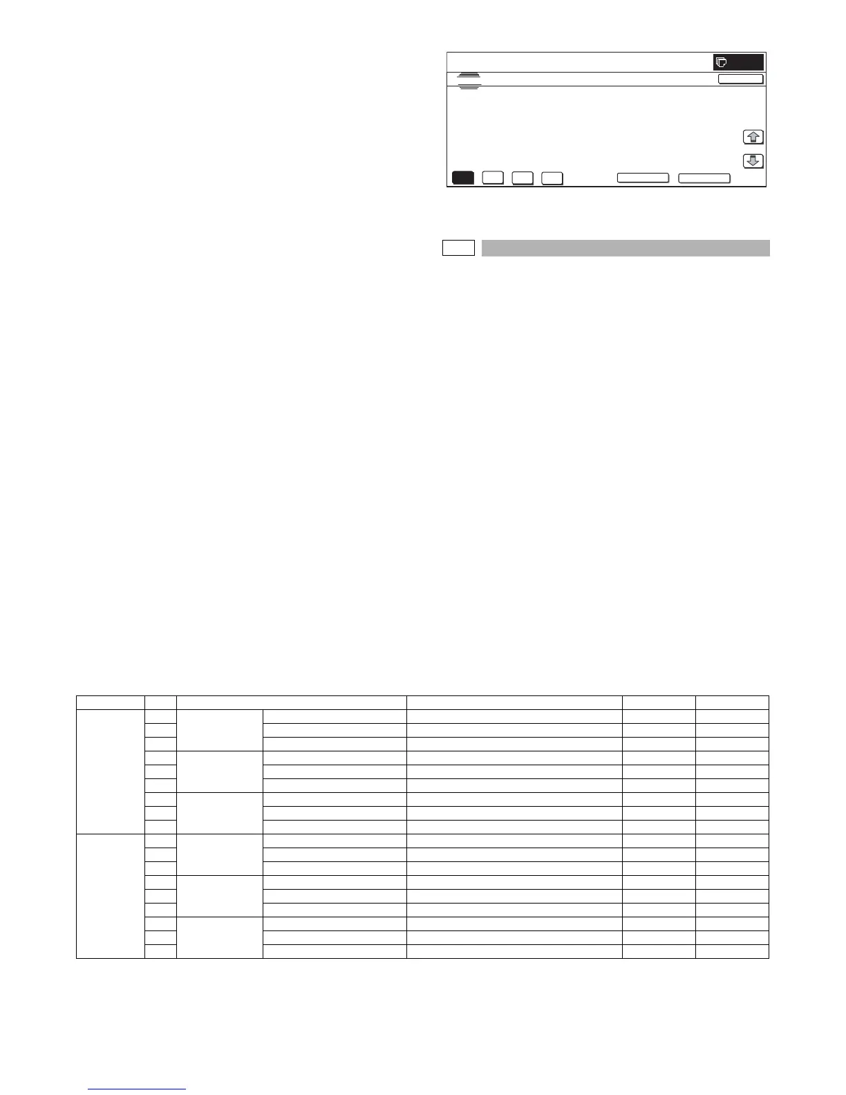
SIMULATION
NO. 50-24
TEST
AUTO REGISTRATION DATA DISPLAY
REG_EXE_CNT 00000000
REG_SUC_CNT 00000000
00000000
REG_CNT
1/1
0
CLOSE
BACK
Item Display item Description Set range Default value
FAX send A Image loss
setting OC
LEAD_EDGE (OC) OC lead edge image loss setting 0 to 100 30 (3mm)
B FRONT_REAR (OC) OC side image loss setting 0 to 100 20 (2mm)
C TRAIL_EDGE (OC) OC rear edge image loss setting 0 to 100 20 (2mm)
DImage loss
setting SPF
SIDE1
LEAD_EDGE (SPF_SIDE1) Front surface lead edge image loss setting 0 to 100 20 (2mm)
E FRONT_REAR (SPF_SIDE1) Front surface side image loss setting 0 to 100 20 (2mm)
F TRAIL_EDGE (SPF_SIDE1) Front surface rear edge image loss setting 0 to 100 30 (3mm)
GImage loss
setting SPF
SIDE2
LEAD_EDGE (SPF_SIDE2) Back surface lead edge image loss setting 0 to 100 20 (2mm)
H FRONT_REAR (SPF_SIDE2) Back surface side image loss setting 0 to 100 20 (2mm)
I TRAIL_EDGE (SPF_SIDE2) Back surface rear edge image loss setting 0 to 100 30 (3mm)
SCANNER
mode (FAX,
other than
COPY)
AImage loss
setting OC
LEAD_EDGE(OC) OC lead edge image loss setting 0 to 100 0 (0mm)
B FRONT_REAR(OC) OC side image loss setting 0 to 100 0 (0mm)
C TRAIL_EDGE(OC) OC rear edge image loss setting 0 to 100 0 (0mm)
DImage loss
setting SPF
SIDE1
LEAD_EDGE(SPF_SIDE1) Front surface lead edge image loss setting 0 to 100 0 (0mm)
E FRONT_REAR(SPF_SIDE1) Front surface side image loss setting 0 to 100 0 (0mm)
F TRAIL_EDGE(SPF_SIDE1) Front surface rear edge image loss setting 0 to 100 0 (0mm)
GImage loss
setting
SPFSIDE2
LEAD_EDGE(SPF_SIDE2) Back surface lead edge image loss setting 0 to 100 0 (0mm)
H FRONT_REAR(SPF_SIDE2) Back surface side image loss setting 0 to 100 0 (0mm)
I TRAIL_EDGE(SPF_SIDE2) Back surface rear edge image loss setting 0 to 100 0 (0mm)