13
8017171/115Z/V3-0/2019-01/ SICK OPERATING INSTRUCTIONS | VISIC100SF
Subject to change without notice
PRODUCT DESCRIPTION
2.2.2.2 Terminal box
2 variants:
● TB-A1: Terminal box for cable connection. It contains:
– 10 terminals to connect cables provided by the customer.
● TB-A2: Terminal box to connect the VISIC100SF to the power voltage. It contains:
– Power supply filter, terminals and a power supply unit.
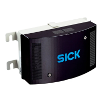
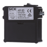
Fig. 5: Terminal box with 24 V power supply for the sensor
Specifications concerning stub lines, see “Stub line length for terminal box on all RS-
485 bus systems”, page 44. must always be adhered to when the VISIC100SF and the
associated terminal box are part of a bus system.
Enclosure cover
Rear enclosure panel with assembly bracket
Electrical screw fittings for cables:
● 3 x 6 ... 11 mm
● 2 x 10 ... 14 mm
Grounding
1
2
4
3
Ready-made connection cables are available for both variants. (Further details on
connection cables, see “Installation material”, page 20).

 Loading...


