25
8017171/115Z/V3-0/2019-01/ SICK OPERATING INSTRUCTIONS | VISIC100SF
Subject to change without notice
INSTALLATION
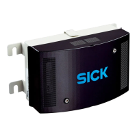
3.4.4 Installing the TAD control unit (optional)
1 Determine the TAD control unit installation location according to project planning.
Dimensions of the TAD control unit, see “Tunnel Adapter Device dimension (all units of
measurement in mm)”, page 99.
2 Drill holes for the TAD control unit as shown in the drilling plan, see “Drilling plan for TAD
control unit for VISIC100SF (all units of measurement in mm)”, page 102.
3 Hammer in the M8 steel tie bar (from mounting kit).
4 Install the TAD control unit.
5 Wiring, see “TAD control unit wiring”, page 35.
3.4.5 Fitting and start-up of the gas sensors (optional)
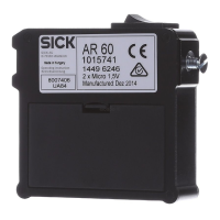
1 Check the tightness of the packaging of the gas sensors after delivery. Send the gas
sensor back to the manufacturer directly when the packaging is not tight.
2 Check the date of manufacture and/or maximum storage duration.
3 Use the SW 8 Allen key to remove the black screw plug on the underside of the
enclosure.
With a separate power supply, the TAD control unit can be installed at a distance of max.
1200 m to the installation location of the VISIC100SF.
WARNING: Hazard through low voltage
▸ Disconnect the 24 V plug connection in VISIC100SF before start-up or exchanging
the gas sensors.
Material required Characteristics Required for
CO, NO,
NO
2
sensors
Compact measuring sensor with
connection cable, calibrated and
temperature corrected
For measuring CO, NO or
NO
2
(optional)
Allen key SW 8 or wrench SW24 Removing seal screw connection
Allen key, SW 4
Screwing gas sensors on or off
Gas sensors
NOTE: Observe sensor service life!
The date of manufacture is marked on the labels of the CO, NO and NO
2
sensors.
Specified service life
[1]
:
● Maximum storage duration: 6 months as from date of manufacture (in unopened
original packaging).
● Maximum service life as from initial start-up: 1 year, replacement or recalibration.
▸ Order spare sensors close to start-up.
▸ Observe storage conditions for sensors, see Technical Data, see “Technical Data”,
page 103
[1] These specifications are based on compliance with the factory calibration. A check and/or exchange is
necessary after longer storage and service life.

 Loading...


