44
8017171/115Z/V3-0/2019-01| SICKO P E R A T I N G I N S T R U C T I O N S | VISIC100SF
Subject to change without notice
INSTALLATION
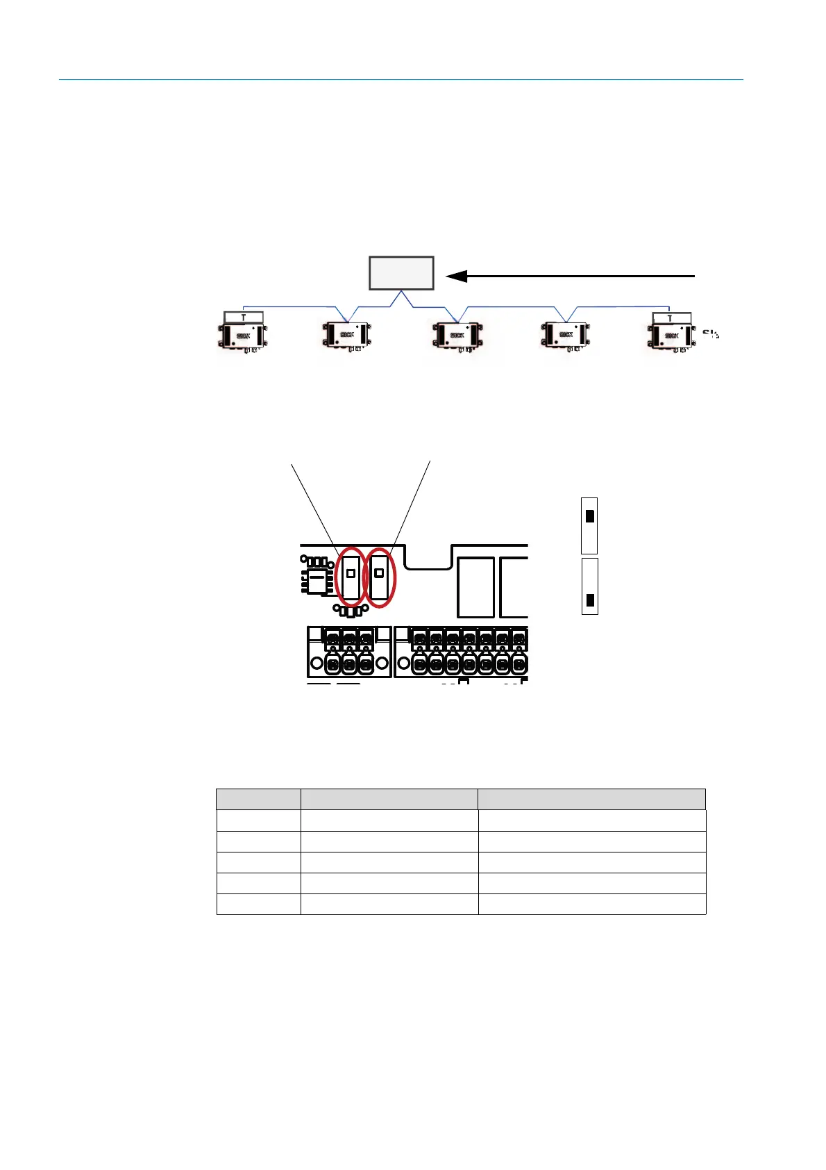
3.7.5 RS-485 - topology and bus termination
When using the RS-485 interface, all field devices are typically connected to one bus
structure (line) (see “Bus topology”, page 44). Each segment can have up to 32 nodes
(master and slaves). The start and end of each segment must be terminated with a bus
termination. A switch on the circuit board serves to set the bus termination on a
VISIC100SF, see “Bus termination on the circuit board”, page 44.
Fig. 30: Bus topology
Fig. 31: Bus termination on the circuit board
3.7.6 Stub line length for terminal box on all RS-485 bus systems
According to the PROFIBUS specification, a maximum total of all stub lines of 6.60 m is
allowed per DP segment. Longer stub lines are allowed for lower data rates.
Table 16: Maximum stub line lengths
If there are more than 32 nodes or the network span is being extended, power amplifiers
(repeaters) allow linking the networks.
Control
station
T = termination
Termination for Modbus and TAD control
unit interface
Switch position:
Off (termination not set)
On (termination set)
Termination for PROFIBUS-DP interface
Bit rate Total capacitance allowed Sum of stub line lengths
1.5 Mbit/s 0.2 nF 6.6 m
500 kbit/s 0.6 nF 20 m
187.5 kbit/s 1.0 nF 33 m
93.75 kbit/s 3.0 nF 100 m
19.2 kbit/s 15 nF 500 m