26
8017171/115Z/V3-0/2019-01| SICKO P E R A T I N G I N S T R U C T I O N S | VISIC100SF
Subject to change without notice
INSTALLATION
Fig. 18: Gas sensor screw plugs
4 Position the gas sensor in any free thread and screw in by hand.
5 Tighten the gas sensor from the outside using a SW4 Allen key.
6 Plug the data cable into one of the two connection terminal strips on the circuit board
(see “Assembly of NO or CO, NO2 gas sensor (optional)”, page 26 marking 3).
7 Close the device:
▸ Tip the measuring unit up and fasten it with the 4 screws.
▸ Position the enclosure cover on the front side of the device.
▸ Screw the two screws on the enclosure cover tight with the SW4 Allen key.
Fig. 19: Assembly of NO or CO, NO
2
gas sensor (optional)
The gas sensor requires a heating up phase of maximum 30 minutes. The Status LED
remains red until the heating up phase has finished.
Do not insert the screw plugs after fitting the gas cells.
Otherwise, no sample gas can reach the electrochemical cells.
1
1
3
2
2
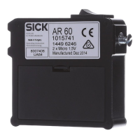
Gas sensors
Connection cables of gas sensors
Connection socket for connection cables of gas sensors

 Loading...


