15
8017171/115Z/V3-0/2019-01/ SICK OPERATING INSTRUCTIONS | VISIC100SF
Subject to change without notice
PRODUCT DESCRIPTION
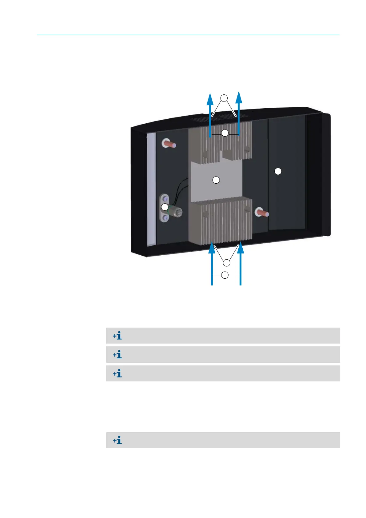
2.2.2.4 Fog dissipation (cover with integrated heating element)
SICK provides a variant with a heating element in the cover for fog dissipation.
Fig. 7: VISIC100SF cover with heating element for fog dissipation
2.2.2.5 Bus interface: PROFIBUS DP-V0, Modbus-RTU
The VISIC100SF is delivered with the following bus interface depending on the
configuration:
–Modbus-RTU (standard)
– PROFIBUS DP-V0 (optional)
1
3
2
Enclosure cover
Heating element
Electrical contacts for heating element
Inlet opening for air to be measured
Flow direction of air to be measured
4
5
5
4
The heating element is integrated in the VISIC100SF cover and cannot be retrofitted
onsite.
The side openings for the air to be measured are closed off on the VISIC100SF version
with fog dissipation.
If the cover is not placed on the measuring unit, error message F004 (heating) is active
because the power supply to the heating is interrupted.
Modbus-RTU is not available when a TAD control unit is used.

 Loading...


