23
8017171/115Z/V3-0/2019-01/ SICK OPERATING INSTRUCTIONS | VISIC100SF
Subject to change without notice
INSTALLATION
2 Drill holes for the VISIC100SF wall bracket as shown in the VISIC100SF drilling plan, see
“VISIC100SF drilling plan (all units of measurement in mm)”, page 100.
3 Hammer in the M8 steel tie bar (from mounting kit).
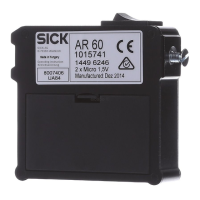
Fig. 15: Assembly - rear enclosure panel
4 Fit the rear enclosure panel.
5 Hinge the measuring unit in.
6 Wiring, see “VISIC100SF wiring”, page 28.
7 Start-up, see “Start-up”, page 37.
8 Screw the measuring unit on.
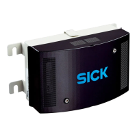
9 Fit the enclosure cover.
Information for loosening the enclosure cover:
Assembly bracket
Hinge fixture for the measuring unit
After loosening the two screws, removing the enclosure cover could be somewhat
sluggish. Therefore, the enclosure cover side panels are extended on the sides and
serve as handles.
If the enclosure cover was placed on the measuring unit while the VISIC100SF was
open, it can be easily removed by pressing the loosened screws against the measuring
unit.
Carefully fold the measuring unit open. The cable connections can cause the hinge
fixture to unhook from the hinge rail.

 Loading...


