91
8017171/115Z/V3-0/2019-01/ SICK OPERATING INSTRUCTIONS | VISIC100SF
Subject to change without notice
MAINTENANCE
Fig. 89: Activating the setting range via menu item “Maint”
5 Tip measuring unit up.
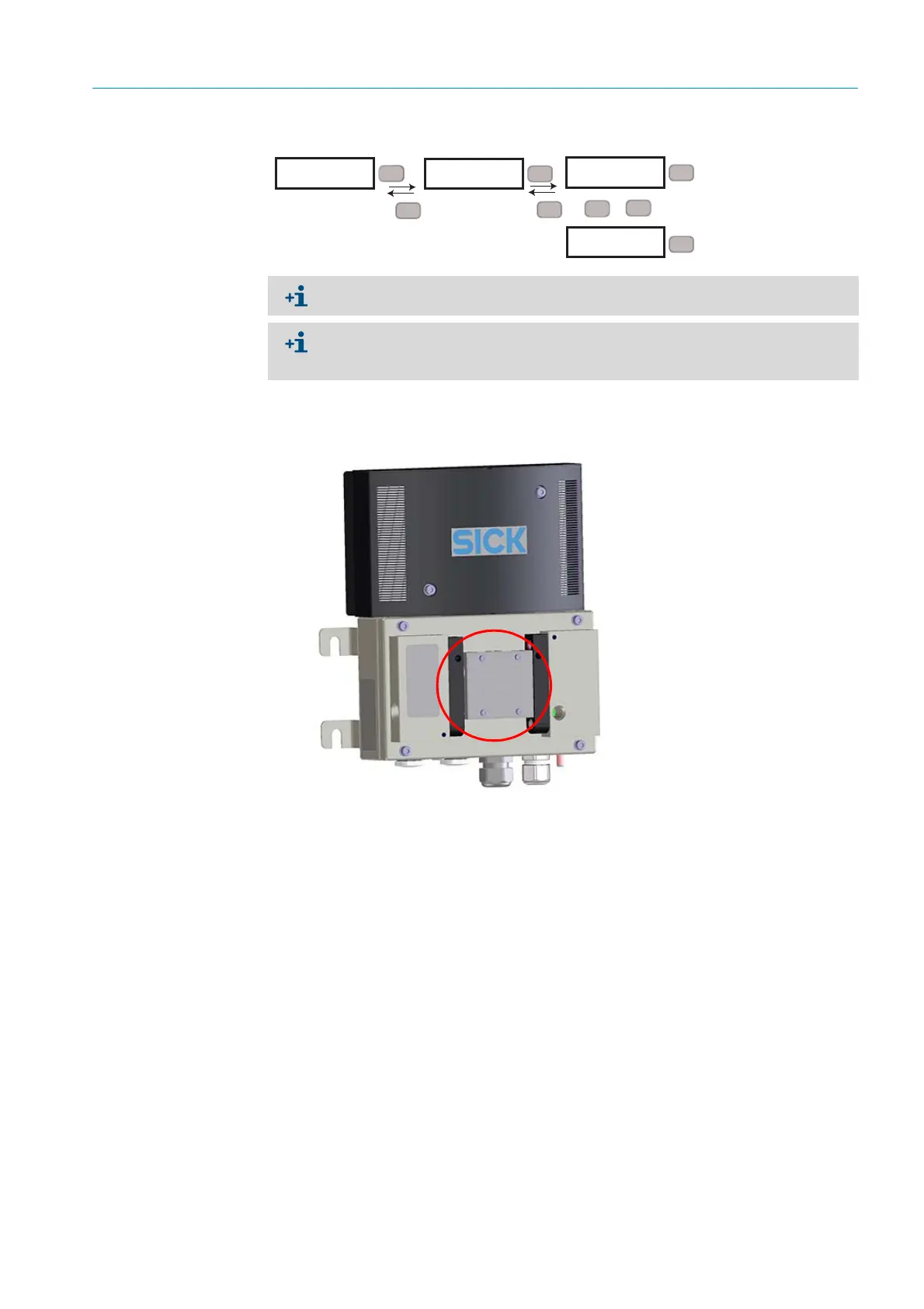
6 Insert the test tool between sender and receiver.
Fig. 90: Test tool positioning
7 The test tool shows the rated value.
8 Open the measuring unit again and read the actual value on the display.
9 Allowed deviations:
– Allowed deviation from actual value: ± 1/ km.
10 If the actual value is within the tolerance, remove the test tool and set the Maintenance
mode to inactive again.
11 Close the device and attach enclosure cover.
Actual value outside tolerance limits
1 Clean all optical interfaces on the device and on the test tool.
2 Check that the test tool is inserted correctly.
3 Repeat the test.
4 Actual value is still outside the tolerance limit: If possible, insert the test tool in other
devices to exclude a defect of the test tool.
5 Replace the measuring unit or send it to SICK for repair.
RUN
X
XXX
Set
SET
Maint
Esc
Set
SET
inact.
>
>
SET
active
Esc
Set
Set
2 s
Mode “active” is reset to “inactive” after 30 minutes.
The malfunction relay is activated when mode “active” is set. The Status LED is red, the
analog outputs output 1 mA and the field bus interfaces signal an error. The Maint LED
on the circuit board is green.
 Loading...


