SYSTEM DESCRIPTION 3
8026362 / V1-0/2022-03|SICK
Subject to change without notice
SUPPLEMENTARY OPERATING INSTRUCTIONS | VMS4100/5100
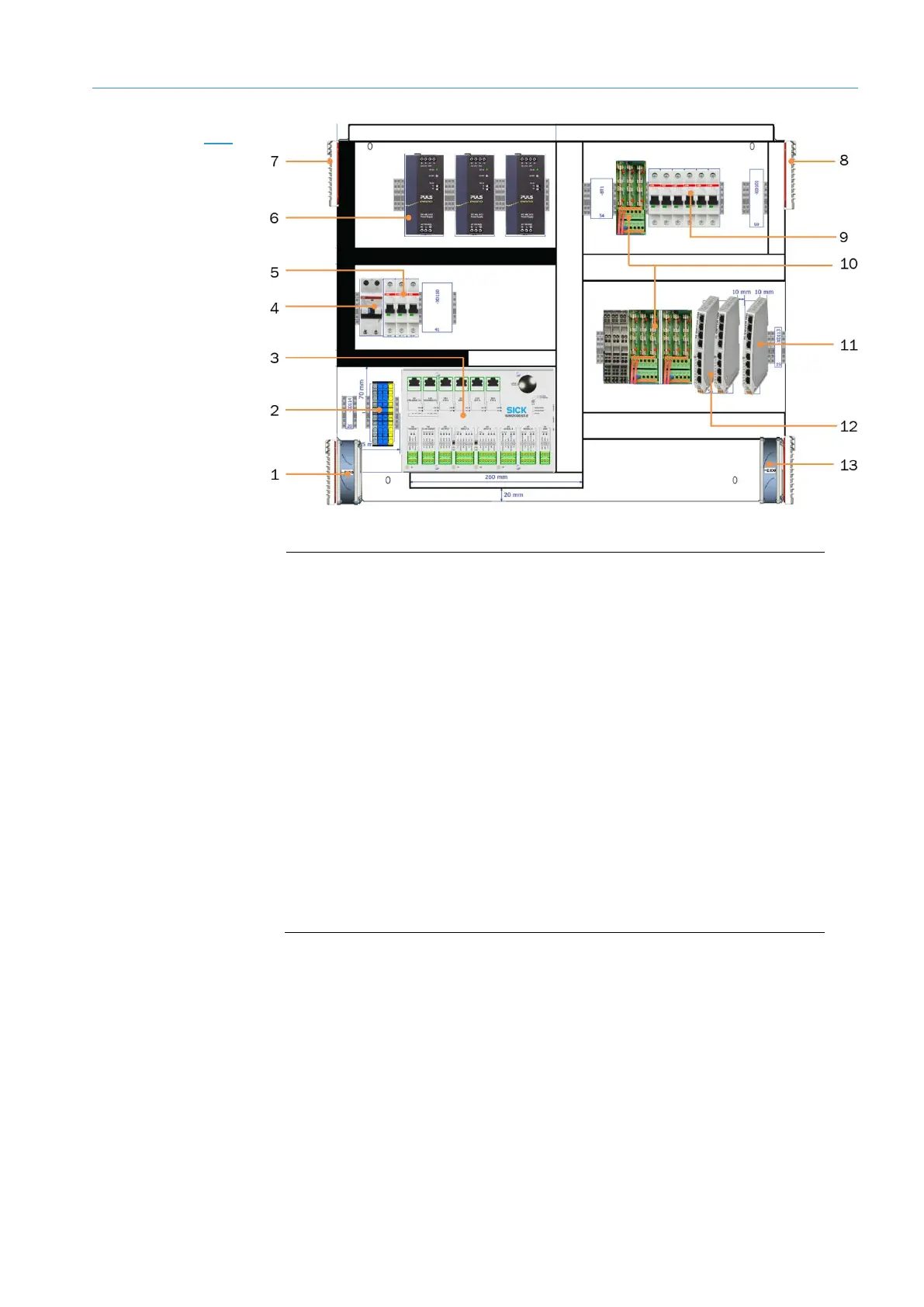
Fig. 7: Cabinet for VMS4100/5100 with LFT Ethernet switch
Legend
1 Air inlet for cooling (with filter mat and cooler)
2 Terminals for voltage supply IN (100–264 V AC / 50–60 Hz)
3 SIM2000-2 Prime controller with alibi memory
4 RCD (residual current device) for protective contact plug
5 Circuit breaker
6 Power supply unit for supplying voltage to the SIM2000-2 Prime controller
and 2D LiDAR sensor
7 Air outlet for cooling (with filter mat)
8 Air outlet for cooling (with filter mat)
9 Circuit breaker
10 Terminals (24 V DC) and fuse module OUT
11 LFT Ethernet switch for connecting the LFT components
12 Ethernet switches for connecting additional sensors
13 Air inlet for cooling (with filter mat and fan)
• The cabinet also contains an LFT Ethernet switch for connecting LFT-relevant system
components.
• A manipulation protective plate protects the LFT Ethernet switch installed in the
cabinet against disassembly and removal of the connecting cables.
Cabinet with
LFT Ethernet switch