05.05 Connections
Siemens AG 6RX1700-0AD76 6-67
SIMOREG DC Master Operating Instructions
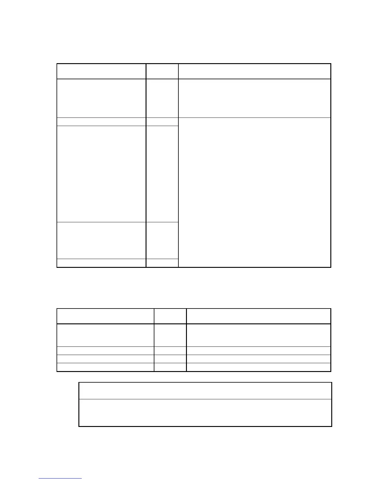
Binary control inputs
(see also Section 8, sheet G110)
Module C98043-A7001 (CUD1)
Function Terminal
X171
Connection values/Remarks
Supply (output) 34 24V DC, short circuit proof
max. load 200mA (terminals 34, 44, and 210 combined),
internal supply with respect to internal ground
Ground digital M 35 Overload response: Error signal F018
Warning signal A018
Select input binary 1 36
Power On / Shutdown
H signal: Power ON
Line contactor CLOSED +
(with H signal at terminal 38),
acceleration along ramp-
function generator ramp to
operating speed.
L signal: Shutdown
Deceleration along ramp-
function generator ramp to
n < n
min
(P370) + , controller
disable + line contactor OPEN.
See Section 9.3 for exact
function description.
37
Enable operation
H signal: Controller enabled
L signal: Controller disabled
See Section 9.3.4 for exact
function description
38
Select input binary 2 39
H signal: +13V to +33V
L signal: – 33V to +3V or terminal open
8.5mA at 24V
Safety shutdown (E-STOP)
(see also Section 9.8 and Section 8, sheet G117)
Module C98043-A7002 or A7003 power interface
Function Terminal
XS
Connection values/Remarks
Supply for safety shutdown (output) 106 24V DC, max. load 50mA, short-circuit-proof
Overload response: Error signal F018
Warning signal A018
Safety shutdown switch 105 I
e
= 20mA
Safety shutdown pushbutton 107 NC contact I
e
= 30mA
Safety shutdown Reset 108 NO contact I
e
= 10mA
NOTICE
Both 105 + 106 terminals or 106, 107 + 108 terminals can be used! Combined use of terminals
105 – 108 will result in a malfunction.
Terminal 105 is connected to terminal 106 in the state as delivered.

 Loading...