Start-Up 05.05
7-56 SIEMENS AG 6RX1700-0AD76
SIMOREG DC Master Operating Instructions
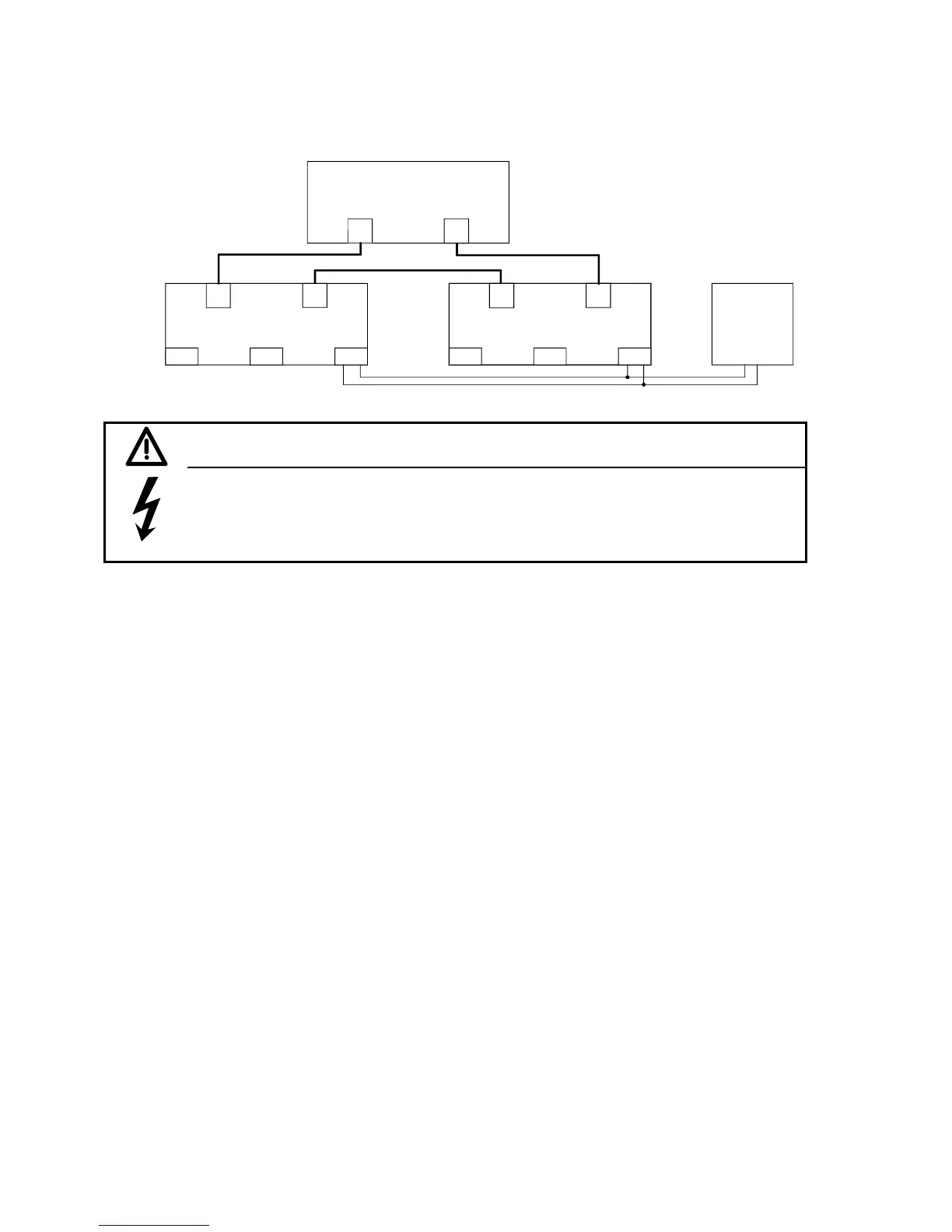
Recommended circuit for connecting SCB1 to SCI1 and SCI2 using fiber optic cables:
SCB1
SCI2
SCI1
U121 U125
U425
U421
U435 U431
X427 X437
24V
X428X429 X438X439
WARNING
If the 24 V voltage supply for an SCI slave fails which data are being exchanged between the
SCB1 and an SCI, then the "1" signal applied at a binary input is sent to the SCB1 or
SIMOREG as an "0" shortly before the power finally fails.
In contrast, the "1" remains applied in the SIMOREG in the event of an interruption in the fiber
optic connection.
If an external voltage (logical "1") has already been applied to a binary input when the electronics
supply voltage is switched on, this status will not be registered until the external voltage is
disconnected and reconnected again.
7.7.8.1 Diagnostic tools:
LED display on SCB1:
LED on Reset state
LED flashing Normal operation
LED off Error
LED display on SCI1 or SCI2 slave:
LED on Reset state
LED flashing 12Hz frequency No telegram traffic (e.g. fiber optic cable not
connected)
5Hz frequency Faulty telegram traffic (e.g. fiber optic ring
interrupted or other slave has no supply
voltage)
0.5Hz frequency Normal operation
LED off Error
Details about fault or alarm messages which may occur in relation to SCB1 or SCI (F070 to F079
and A049 and A050) can be found in Section 10.

 Loading...