05.05 Start-Up
SIEMENS AG 6RX1700-0AD76 7-29
SIMOREG DC Master Operating Instructions
7.7.3 Sequence of operations for starting up CAN bus boards (CBC):
1 With the power supply switched off, insert the board with adapter board (ADB) into the slot.
For board mounting instructions, see Section 5.3.2 , Mounting Optional Supplementary
Boards.
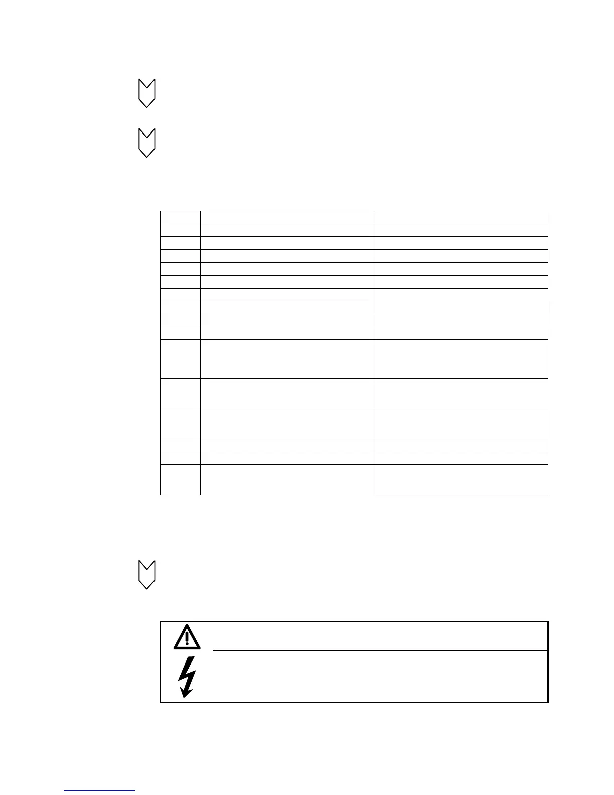
2 The following are important communication parameters. Index 1 of each parameter is set for
the 1
st
communication board (1
st
CB) and index 2 for the 2
nd
communication board (2
nd
CB):
Exception: In parameter U721, i001 to i005 are applicable to the 1
st
CB and i006 to i010 to
the 2
nd
CB (indices 3 to 5 and 8 to 10 are reserved).
The meaning of the parameters also differs depending on the setting of U721, i.e. CAN-
Layer 2 (U721=0) and CANopen (U721=1):
CAN-Layer 2 CANopen
U711 Basic identifier for PKW Request/PKW Response 1
st
Receive-PDO
U712 Basic identifier for PZD Receive 2
nd
Receive-PDO
U713 Basic identifier for PZD Send 3
rd
Receive-PDO
U714 Number of PZD for PZD Send 4
th
Receive-PDO
U715 Updating rate for PZD Send 1
st
Transmit-PDO
U716 Basic identifier for PZD Receive-Broadcast 2
nd
Transmit-PDO
U717 Basic identifier for PZD Receive-Multicast 3
rd
Transmit-PDO
U718 Basic identifier for PZD Receive-Internode 4
th
Transmit-PDO
U719 Basic identifier for PKW Request-Broadcast Response to Life Time Event
U720 Baud rate when U721.002 or U721.007 = 0:
0=10kbit/s, 1=20kbit/s, 2=50kbit/s, 3=100kbit/s,
4=125kbit/s, 5=250kbit/s, 6=500kbit/s,
7=Reserved, 8=1Mbit/s
Baud rate when U721.002 or U721.007 = 0:
0=10kbit/s, 1=20kbit/s, 2=50kbit/s, 3=100kbit/s,
4=125kbit/s, 5=250kbit/s, 6=500kbit/s,
7=Reserved, 8=1Mbit/s
U721.01
or
U721.06
0 = Functionality according to Layer 2 of ISO-OSI-
7 Layer Model
1 = Functionality according to Layer 7 of ISO-OSI-
7 Layer Model (CANopen)
U721.02
or
U721.07
Bus timing (this should not be changed) Bus timing (this should not be changed)
U722 Telegram failure time (0 = deactivated) Telegram failure time (0 = deactivated)
P918 Bus address (node ID) Bus address (node ID)
P927 Parameterizing enable (required only in cases
where parameter values must be altered via the
CAN Bus)
Parameterizing enable (required only in cases
where parameter values must be altered via the
CAN Bus)
The process data of the 1
st
or 2
nd
communication board are connected by means of the
appropriate connectors and binectors (see Section 8, function diagrams Z110 and Z111)
For meaning of bits of control and status words, please see Section 8, Sheets G180 to
G183.
3 Turn the electronics supply voltage off and on again or set U710.001 or U710.002 to "0" to
transfer the values of parameters U711 to U721 and P918 to the supplementary board.
Note: The initialization process may interrupt the communication link to a supplementary
board which is already operational.
WARNING
This initialization process will interrupt the communication of any supplementary
board that has already been started up.

 Loading...