Function diagrams 05.05
8-102 SIEMENS AG 6RX1700-0AD76
SIMOREG DC Master Operating Instructions
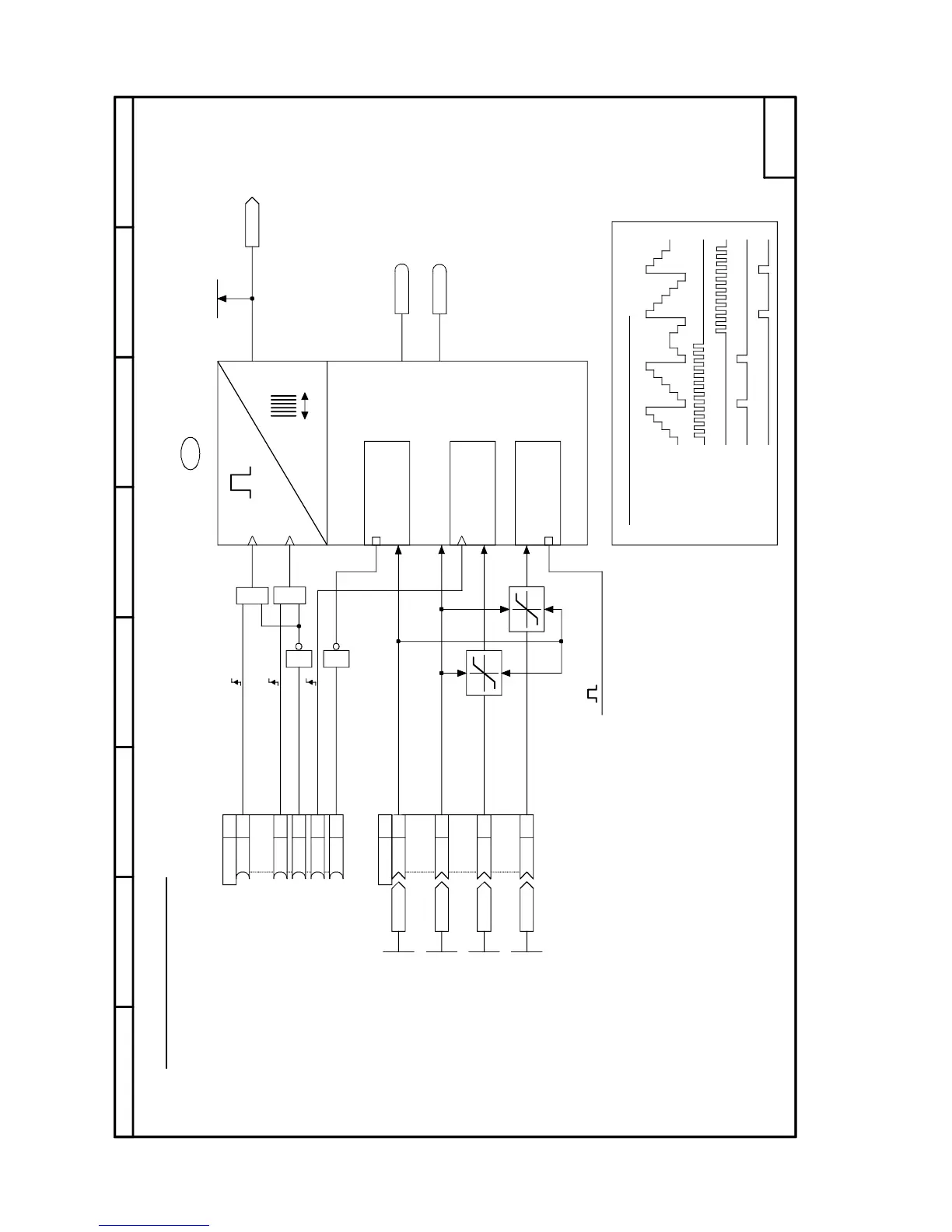
Sheet B196 16-bit software counter
87564321
- B196 -
89
.01
.03
.04
&
1
&
1
.02
.01
.02
.03
.04
.05
<1>
77
2
2
3
4
5
6
7
2
3
4
5
6
7
3
4
2
3
2
3
4
5
6
7
2
4
5
6
7
<2>
<2>
K9443
K9444
U316
K
K
K
9441
U317
B
B
UP
DOWN
B
B
B
0
0
0
0
1
K
9442
9443
9444
K9441
K9442
K9445
0...65535
n314
OUT
0...65535
U315.01 (0)
0...65535
U315.02 (65535)
0...65535
U315.03 (0)
0...65535
U315.04 (0)
B9290
B9291
POWER ON
FS
FS
Set counter
to minimum
value
Set counter
to start
value
Set counter
to setting
value
Binary output
(Binary code)
Count up
Count down
Stop counter
Set counter
Enable counter
Minimum value
Maximum value
Setting value
Start value
Minimum counter value
Maximum counter value
Counter setting value
Counter start value
Priority:
1. Enable counter
2. Set counter
3. Stop counter
4. Count up / down
Overflow
Underflow
from sheet B110
Counter output
Count up
Count down
Overflow
Underflow
Example: Minimum value = 2, Maximum value = 7
16-bit software counter
Maximum counting frequency = 1 / scanning time
<3>
<1> The counter is set to the start value after POWER ON
<2> The start and setting values are limited to the range (minimum value..maximum value)
<3> Example: The counter operates in the time slice 1
→
max. counting frequency = 300 Hz
Note: The sampling time and sequence of the upstream signal processor
must also be taken into account

 Loading...