9
Thermal Overload Protection (49-1, 49-2)
7UT51 v3
108 PRIM-2330C
9.2 Normal Operational
Status
The thermal overload elements (49-1, 49-2) can be
Non-Existent/Disabled,
or a choice is made as to
which side (or winding) is to be monitored. A common
practice is to monitor the lowest rated winding. The
choices are made in addresses 7824 and 7825.
Once a thermal overload element is referenced to a
side
, it can be configured. Its normal status is set in
Address 2401 (for the 49-1 element) or 2501 (for the
49-2 element).
9.3 Pickup Characteristic
and Warning Levels
9.3.1 Maximum Continuous
Overload Current
The maximum allowed continuous overload current is
specified in Address 2402 (or 2502) as a multiple or
fraction of the rated nominal current of the protected
object.
From the manufacturer of the protected object, obtain
the protected object’s maximum continuous thermal
overload current (
I
max
) and rated nominal current (
I
n
),
then calculate the “k factor” using the following
equation:
(9.3)
If the manufacturer’s data for
I
max
is not available, a
typical value is 1.1, which would require the load
current to exceed 110% of the rated nominal current
before a 49 pickup could occur.
9.3.2 Time Constant
τ
ττ
τ
Because the appropriate time-until-pickup depends on
a thermal time constant,
τ
ττ
τ, which is related to the
maximum current the protected object can tolerate for
a short duration (often called the “
1 second current
”).
The unit of τ
ττ
τ is
minutes
. Consult the documentation of
the protected object to obtain the duration and current
of an allowed overload, then calculate τ
ττ
τ using the
following equation:
(9.4)
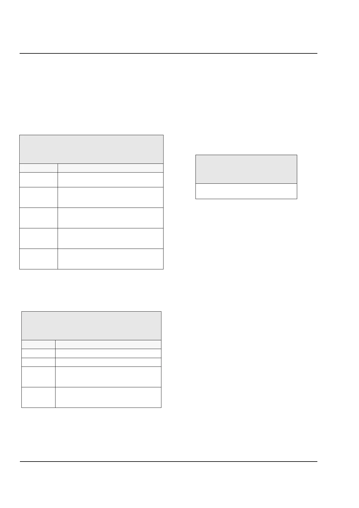
7824 49 Therml1
7825 49 Therml2
Existence and monitored winding (or side) of each thermal
overload protection element (49
-
1 and 49
-
2).
Option Description
Non
-
Existent/
DISABLED
49
-
1 (or 49
-
2) element does not exist
(default).
REFERENCE
SIDE 1
49
-
1 (or 49
-
2) element exists and monitors
Winding 1 (or Side 1) of the protected
object.
REFERENCE
SIDE 2
49
-
1 (or 49
-
2) element exists and monitors
winding 2 (or Side 2) of the protected
object.
REFERENCE
SIDE 3
49
-
1 (or 49
-
2) element exists and monitors
winding 3 (or Side 3) of the protected object
(7UT513 only).
VIRTUAL
OBJECT
49
-
1 (or 49
-
2) element exists and monitors
a separate, object (only available when a
7UT513 is protecting a two
-
sided object).
2401 49Therml1
2501 49Therml2
Normal operational status of each thermal overload
element (49
-
1 or 49
-
2).
Option Description
ON 49
-
1 (or 49
-
2) element is active (default).
OFF 49
-
1 (or 49
-
2) element is inactive.
BLOCK
TRIPPING
49
-
1 (or 49
-
2) element is active except that
trip contacts and signal contacts will not
respond to this 49 element’s trip events.
ALARM
ONLY
49
-
1 (or 49
-
2) element is active except that
trip and signal contacts operate only for this
49 element’s alarm events.
2402 K
-
fctr 1
2502 K
-
fctr 2
Ratio of maximum continuous thermal
overload current to rated current: I
MAX
/ I
N
Range: 0.10
–
4.00 (unitless)
Default: 1.10
k
I
max
I
n
----------
=
τ
allowed duration in minutes
short-term current
continuous current
--------------------------------------------
⎝⎠
⎛⎞
2
×=
 Loading...


