7UT51 v3
Transformer Differential Protection (87T and 87HS)
4
PRIM-2330C 43
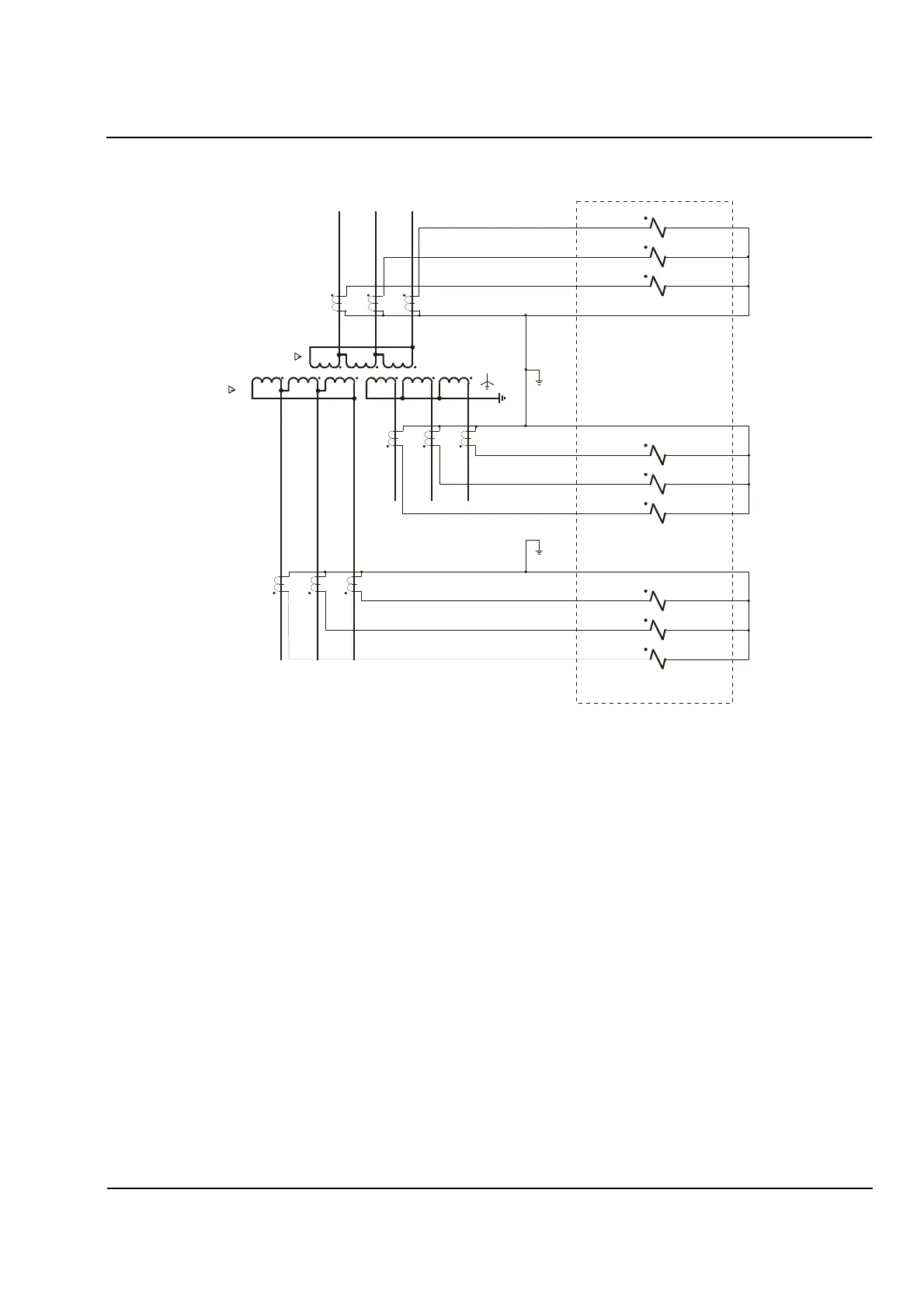
Figure 4.5
Typical CT Wiring for a Three
-
Winding, Delta
-
Wye
-
Delta Transformer
4.2 Describing the
Transformer
This section describes the addresses used to provide
the relay with information about the protected
transformer, including:
• The number of windings the transformer has
• The rated frequency of the protected transformer
• The rated phase-to-phase voltage (V
n
) of each
winding of the protected transformer
• The rated apparent power (VA) of each winding of
the protected transformer
• The phase shift (lag angle relative to Winding 1) of
winding 2 (and, if applicable, of winding 3) of the
protected transformer
In the following discussion, “Winding 1” is the
reference winding, which is usually the high-side
winding of the protected transformer. If a CT is
installed in the ground lead of a grounded wye
connected transformer, that winding must be used as
the reference winding in order to ensure increased
ground-fault sensitivity by correction of the zero
sequence current.
Primary
Secondary
Tertiary
7UT513
a
a'
A
b
b'
B
c
c'
C
I
A
I
B
I
C
I
a
I
a'
I
b
I
b'
I
c
I
c'
3A1
3A2
2A1
2A2
1A1
1A2
3B1
3B2
2B1
2B2
1B1
1B2
3D1
3D2
2C1
2C2
1C1
1C2
 Loading...


