7UT51 v3
Installation and Servicing
17
PRIM-2330C 181
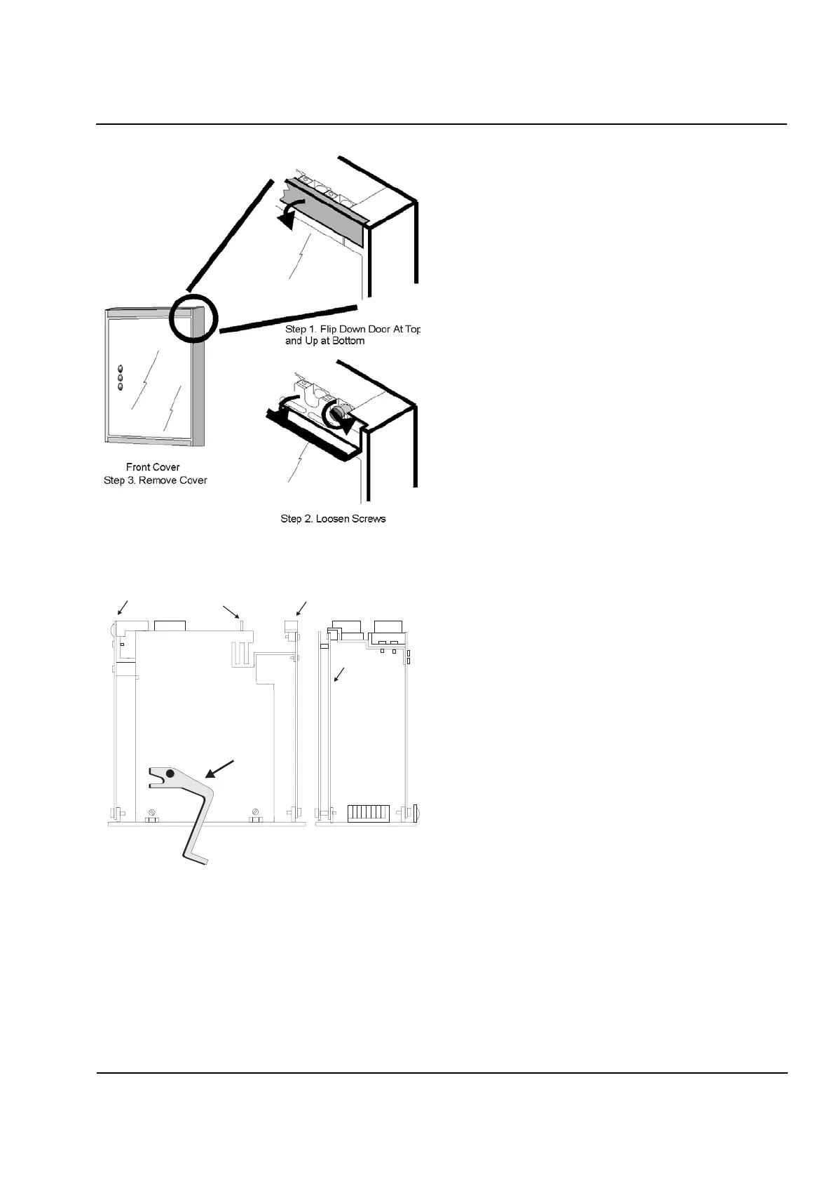
Figure 17.3
Front Cover Removal
Figure 17.4
Release Lever Operation
17.4 Mounting the Relay
Case
The procedure for mounting the relay case is as
follows:
1. Cut and drill the mounting panel to the dimensions
shown in Figure 17.6 (for the 7UT512 relay) or
Figure 17.7 (for the 7UT513 relay).
2. To make the case lighter and thus easier to
handle, remove the relay module(s) from the case.
3. Insert the relay case into the panel from the front,
so that the case’s mounting flange is on the
outside of the panel. Make sure that the case is
right-side up (the letters and numbers of the labels
on the back of the case should be right-side up).
Secure the case to the panel with four screws or
bolts.
4. Connect a braided ground strap to either of the
grounding screws on the back of the case
(see Figure 17.5).
5. Insert the relay module(s) back into the case and
re-attach the front panel.
Releasing Lever
View From Top
CPU
Board
Power Supply (SV)
Board
GEA
Board
ZEA
Board
AB
C
D
Basic module
Additional I/O Module
(7UT513 only)
 Loading...


