7UT51 v3
Field Testing and Commissioning
18
PRIM-2330C 199
The symbols for the side or winding of the protected
object are W1, W2, W3*, WA*, WB* or I1, I2, I3, IA, IB.
The symbols for the phase reference are Ia, Ib, Ic or
L1, L2, L3 or PhA, PhB, PhC.
Compare the displayed currents with the test currents.
If deviations occur that cannot be explained by
tolerances, either the connection or the test
arrangement is wrong.
• Disconnect the protected object (shut down the
generator) and ground.
• Check connections and test arrangement
• repeat test
18.3.1 Tests Related to All
Applications
Connect the test equipment such that the test current
will flow from Side 1 to Side 2 of the protected object.
Side 3 (if applicable) must be isolated. Since the test
current is flowing from Side 1 to Side 2, all results that
concern Side 3 will have the message “****”.
If the current magnitudes are consistent, page on to
Address 4121. The phase angle relations are
displayed. It is not necessary to request a new
measurement. The phase angle differences are
displayed in 30
o
increments; therefore small
deviations (up to +/- 10
o
) are tolerated. When the
measured angle is outside of this tolerance range, the
display shows “inval” The angle differences are
defined for clockwise phase rotation. The angle
differences of the three currents of Side 1and 2 will be
as follows:
If the values are not correct, wrong polarity or phase
interchange at side (or winding) 1 or 2 is the cause:
• Disconnect the protected object (shut down
generator) and ground.
• Check connections and test arrangement
• Repeat test by renewed measurement request
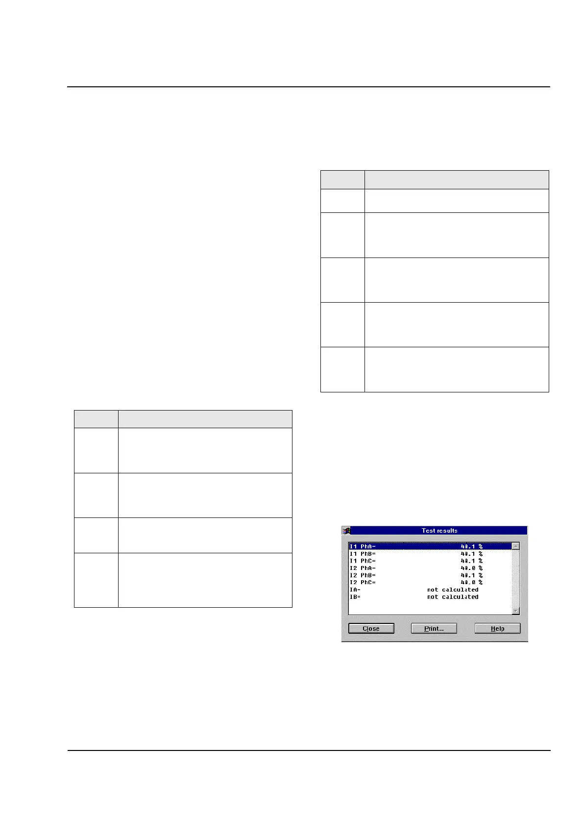
Figure 18.3
WinDIGSI Screen Example of Measured
Current Test for Each Phase on Each Side
Address Test Messages
4101
Te s t D iff
I1 L1=12.3 (e.g.) This is the measured
current of Side 1, phase 1 referred to the
rated relay current
Te s t D iff
Invalid
-
Error message after measurement
request, invalid result (e.g. because of
network fault)
Te s t D iff
Current Too Small
-
All currents are too
small for evaluation
Te s t D iff
I1 L1 = ****
-
current for an individual
measurement is too small or no current.
Further currents can be read by using the
No key (on the front panel).
Address Test Message
4121
Test Angle L Test? Confirm with the Yes key or
abort with the No key.
4121
Test Angle L
I1L2
-
I1L1=240
o
-
display of phase angle
between the currents of Side 1, phase L2
against phase L1, should be 240
o
4121
Test Angle L
I1L3
-
I1L1=120
o
-
display of phase angle
between the currents of Side 1, phase L3
against phase L1, should be 120
o
4121
Test Angle L
I2L2
-
I2L1=240
o
-
display of phase angle
between the currents of Side 1, phase L2
against phase L1, should be 240
o
4121
Test Angle L
I2L3
-
I2L1=120
o
-
display of phase angle
between the currents of Side 1, phase L3
against phase L1, should be 120
o
.
 Loading...


