7UT51 v3
Application Examples
3
PRIM-2330C 35
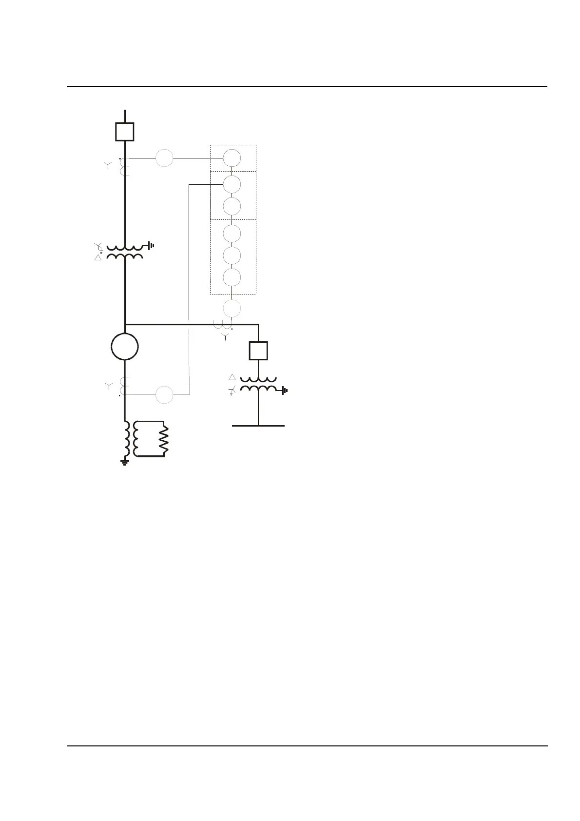
Figure 3.8
Protection of Unit Connected Generator and
Main Power Transformer with Overcurrent
Backup for Unit Auxiliary Transformer
3.4 Bus Protection
Because of the very high fault currents associated with
bus faults, primary bus protection is normally
implemented with a high-impedance type differential
relays. However, when fault currents are of lower
magnitudes, as they tend to be with radial distribution
systems, the 7UT513 can be used in bus protection
schemes. Figure 3.9 shows a typical two-bus radial
distribution system with a tie breaker for greater
reliability. Because the CT ratios of the source
breakers, tie breaker, and feeder breakers are typically
different from one another, a 7UT513 is required since
it has three sets of phase-current inputs. The
supply-branch CTs are connected to one set of
phase-current inputs, the tie breaker CTs to another,
and the feeder breaker CTs (all of the same ratio and
tied together external to the relay) to the third. Backup
overcurrent protection (not shown in the figure) can
also be implemented internally by the 7UT513s.
other
other
49-1
49-2
50
51
52
W1
7UT513
W2
W1
W2
W3
3
3
3
52
G
other
Aux Bus
87
87
HS
W2/W3 (LV)
W1 (HV)
 Loading...


