7UT51 v3
Bench Testing
16
PRIM-2330C 173
16.7 Thermal Overload
Protection Testing
Two thermal overload protection functions are
available, each of which can be assigned to any
desired side of the protected object or to the virtual
object. The relay is programmed with the side of the
protected object of the first overload protection
(Address 7824) and the second overload protection
(Address 7825). Each overload protection must be
parameterized as operative,
On
, in addresses 2401
and 2501.
Testing of 49-1 and 49-2 may cause operations of 87,
87HS, 50/51, and 50HS. If this occurs, set to
Off
to
disable the differential elements and backup
overcurrent elements.
Note:
After testing 49-1 and 49-2, these addresses
must be reset to the desired values.
The basis current for the detection of overload is the
rated current of the protected object.
For use as transformer protection, the basis current is
the rated current of the protected transformer winding.
If the windings have different MVA ratings, then the
overload function always refers to the rated current of
the respective winding. It is assumed that the
transformer data for each winding have been correctly
parameterized.
For use as generator or motor protection, overload
protection is based on the rated current of the
protected machine which is derived from the data
entered in Address Block 1200.
For use as branch protection, overload protection is
based on the rated current of the branch point entered
in Address Block 1300.
If the overload protection is used for a virtual object,
overload is based on the rated current of the virtual
object entered in Address Block 1400.
Address 2406 is important for testing 49-1. If
Address 2406 = Average , this procedure requires
that a single current source be connected to inject
current in all three phases associated with the winding
or object. If Address 2406 = [ MAX] or [ @ Imax],
then current injection into any one phase is sufficient.
The same comments for Address 2406 apply to
Address 2506, which is associated with 49-2.
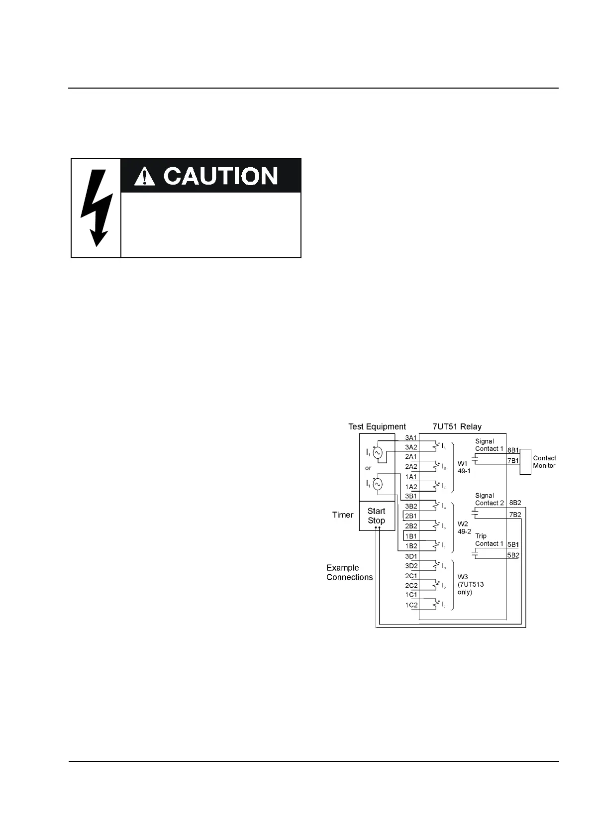
The same 7UT51 connections can be used for all of
the 49 tests. Figure 16.13 shows the connections for
the following example. Element 49-1 is protecting
Winding 1 using either the maximum calculated
temperature for each phase current
(Address 2406 = MAX) or the calculated
temperature based on the highest phase current
(Address 2406 = @ Imax). Element 49-2 is
protecting Winding 2 using the average of the
calculated temperatures of the phases.
For the example, this procedure requires current be
injected in all three phases of Winding 2 to test 49-2.
Current injection for Winding 1 can be either
single-phase or include all three phases (single-phase
is shown for simplicity).
Figure 16.13
Test Connections for Testing 49
-
1 and 49
-
2
First identify the applicable winding for current
injection. Then, based on Address 2406 or
Address 2506, connect the winding phases for either
single-phase or three phase current injection.
Test currents larger than four (4)
time In or 15A (Sensitive input) may
overload and damage the relay if
applied continuously.
Observe a cooling down period!
Θ
ΘΘ
Θ
Θ
 Loading...


