7UT51 v3
Transformer Differential Protection (87T and 87HS)
4
PRIM-2330C 49
The ratio of the interposing transformers is chosen
such that the winding with the lower rating (usually the
tertiary winding of the transformer) is roughly matched
to the winding with the highest rating, i.e. the current
ratio of the interposing transformers should be:
Thus, the winding ratio of the interposing CTs is
where:
N
1
- Number of winding turns on the side facing the
main CTs
N
2
- Number of winding turns on the side facing the
7UT51 relay
The exact current matching is performed when setting
the parameters for this winding.
Example:
The following data should apply for the
winding with the highest power rating:
rated power S
N
=57 MVA
rated voltage U
N
=110 kV
current transformers 300 A/ 1A
The following data should apply for the winding
with the lowest power rating:
rated power S
N
=12.5 MVA
rated voltage U
N
=10 kV
current transformers 800 A/ 1A
This results in a winding ratio of the interposing
transformers of:
which results in a current transformer ratio of:
Thus, a primary rated current of 3636A for the current
transformers is to be set to the protection unit in this
example case.
4.3.4 Orientation of CTs
The orientation of the CTs monitoring each winding of
the protected transformer must be specified in order to
ensure that the correct polarity is used when
calculating the differential currents.
For example, if terminal 3A2 (non-polarity, phase A
input of Winding 1) is connected to the end of the CT
closest to the transformer (as shown in Figure 4.4),
Address 1105 should be set to “
Towards
Transformer.
”
4.3.5 Processing the Zero
Sequence Current
If a winding of the protected transformer has any
connection to ground (as is usually the case for a
wye-winding), there is likely to exist a zero sequence
current in the winding. Any zero sequence current will
by itself cause a differential current for one or more of
the phases (A, B, and/or C). Using the measured
phase currents, the relay can calculate the expected
zero sequence current for each winding and
mathematically
eliminate
it when calculating the
matched currents for the differential protection;
however, if the measured ground current(s) are
available (see Section 4.3.6 on page 50) the relay can
correct
the matched currents, resulting in more
sensitive differential protection.
TR
1
=
S
N
of the high
-
power winding
S
N
of the low
-
power winding
S
N
of the high
-
power winding
S
N
of the low
-
power winding
N
1
N
2
=
S
N
of the high
-
power winding
S
N
of the low
-
power winding
N
1
N
2
=
=
=
12.5 MVA
57 MVA
0.22
≈
11/50 turns
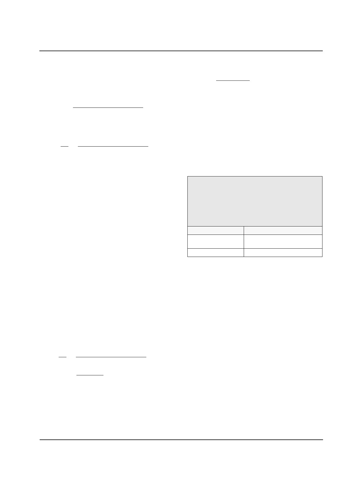
1105 CT1 STARPT (for Winding 1)
1125 CT2 STARPT (for winding 2)
1145 CT3 STARPT (for winding 3, 7UT513 only)
Orientation of which end of each winding’s CTs are
connected to the corresponding non
-
polarity terminal of
the relay’s phase current inputs. For wye connected CTs,
this is the non
-
polarity ends of the CTs, which are usually
connected to a common point (or star
-
point).
Option Description
TOWARDS TRANSF Towards the transformer
(default).
TWDS LINE/BUSBAR Away from the transformer.
800 A/1 A
11/50
= 3636 A/1 A
 Loading...


