16 Bench Testing
7UT51 v3
162 PRIM-2330C
16.3.1 Ideal Through
-
Fault Test
When performing two-source testing, the sources can
be set to create an ideal through-fault condition, in
which case
no differential current is expected.
The
easiest way to test this is to apply the calculated
nominal current (I
Nsec
) on the wye side of the
transformer and 0.58 times calculated nominal current
on the delta side of the transformer as shown in Figure
16.3, Figure 16.4, and Figure 16.5. These test
currents replicate a perfect through current.
I
NsecW1
is the CT secondary, nominal (per unit base)
current of the delta side of the transformer, while
I
NsecW2
is the CT secondary, nominal (per unit base)
current of the wye side of the transformer:
Note:
The values to use for the above equation are
found or entered in Address Block 1100. Be
aware that CT ratios are not entered in this
Address Block if the CTs have a secondary
rating of 5 amps. Instead, the primary current
ratings of the CTs, for the set ratios, are
entered in Addresses 1104, 1124, and 1144.
For CTs with a rating of 5 amps, these
addresses must be divided by 5 amps to obtain
the ratios to use in this equation.
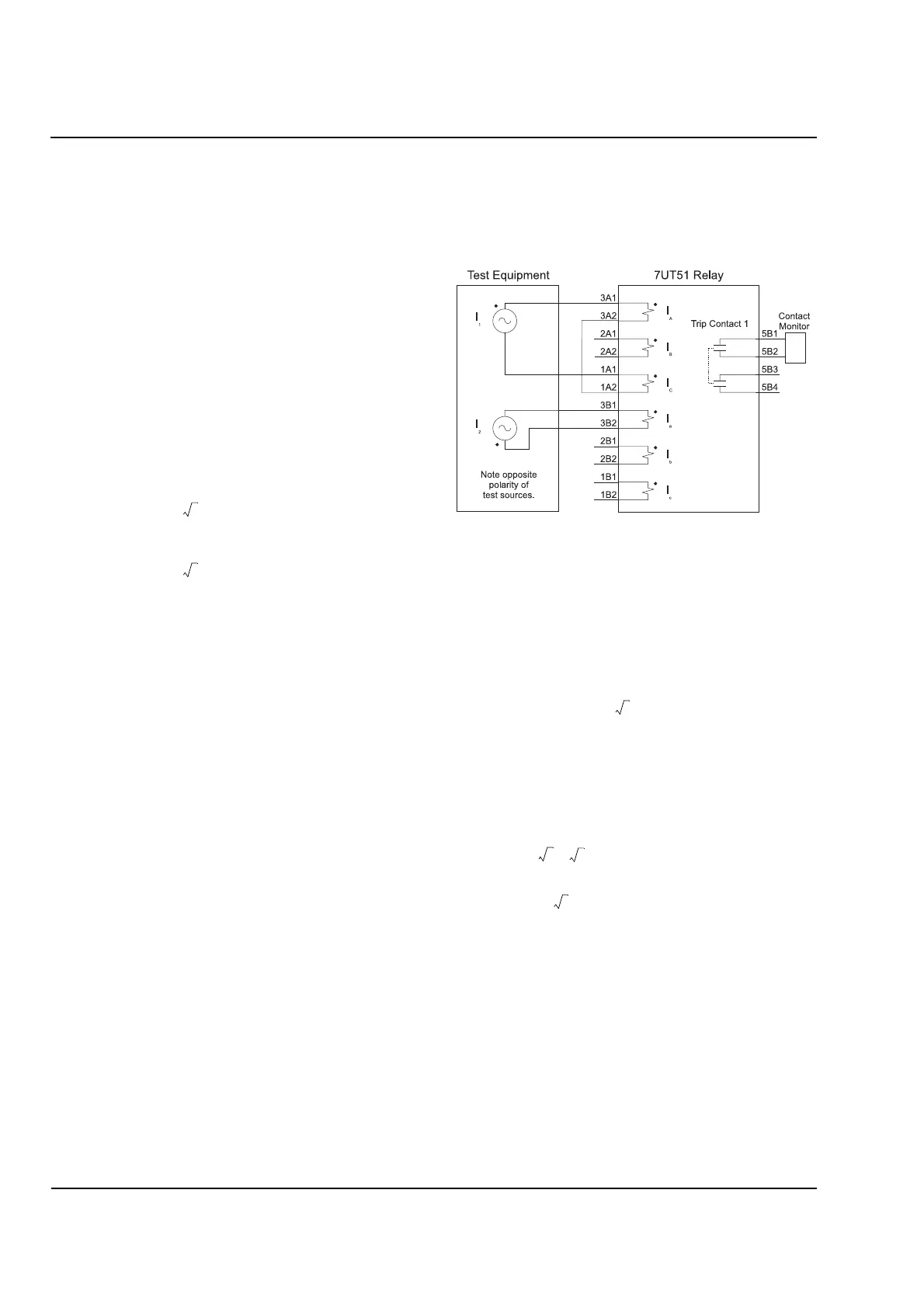
Connect Test Equipment
Connect the test equipment and the relay as shown in
Figure 16.3. The currents I
1
and I
2
must be 180° apart
(±1°) to simulate a through-fault condition.
Figure 16.3
Two
-
Source Through
-
Fault Test for Phase
A-Gnd Fault on Wye Side
Apply Currents
Calculate and apply currents I
1
and I
2
, as shown in
Figure 16.3:
Using the example values from Table 16.2:
Expected Result
If applied accurately, the above currents will result in a
differential of less than 2%. If overcurrent elements are
being used and the overcurrent pickup levels will be
exceeded by one of the test currents, reduce both
source currents proportionally or temporarily turn the
overcurrent off. The same should be considered for
the restricted ground-fault function.
The applied test currents should not cause the relay to
trip or pickup. Confirm that this is true.
I
NsecW1
kVA Rating of Transformer
3
V
L-L,W1
×
CTR
W1
×
-------------------------------------------------------------------=
I
NsecW2
kVA Rating of Transformer
3
V
L-L,W2
×
CTR
W2
×
-------------------------------------------------------------------=
where
V
L
-
L
=Line
-
to
-
Line Voltage in kV
CTR
=CT Ratio
W1
=Data Associated with Winding 1
(Delta
-
side in this example)
W2
=Data Associated with Winding 2
(Wye
-
side in this example)
I
1
1
3
-------
I
NsecW1
=
I
2
I
NsecW2
=
I
1
1
3
-------
45,000 kVA
3138 kV
×
300 5
⁄()×
----------------------------------------------------------
×
1.81 A==
I
2
45,000 kVA
3 24.5 kV
×
1200/5
()×
------------------------------------------------------------ 4 . 4 2 A==
 Loading...


