4
Transformer Differential Protection (87T and 87HS)
7UT51 v3
66 PRIM-2330C
4.11 Single
-
Phase Transformers
Single-phase transformers can be designed with one
or two phases per winding; in the latter case, the
winding phases can be wound on one or two iron
cores. To ensure that optimum matching of the
currents is possible, always use two measured current
inputs even if only one current transformer is installed
on one phase. In the following, the currents are called
I
a
and I
c
.
If two winding phases are available, they may be
connected either in series (which corresponds to a
wye-winding) or in parallel (which corresponds to a
delta-winding). The phase displacement between the
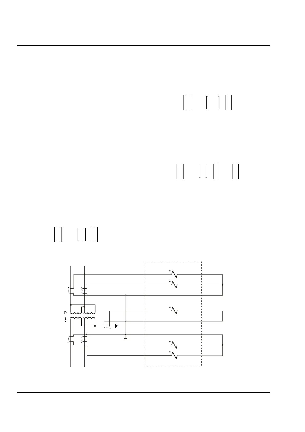
windings can only be either 0° or 180°. Figure 4.14
shows an example of a single-phase power
transformer with two phases per winding.
The matrix equation for computing the matched
currents is the same as for a three-phase transformer,
but since the phase displacement between the
windings can only be 0° or 180°, there are only two
ways to handle the zero sequence current. If the
common of the protected transformer winding is not
grounded, the phase currents can immediately be
used. The current-matching matrix equation is then:
(4.17)
If the common is grounded, the zero sequence current
must be eliminated. The current-matching matrix
equation is then:
(4.18)
The disadvantage of eliminating the zero sequence
current is reduced sensitivity in the event of a
ground-fault in the protected zone (by a factor of 1/2).
Higher ground-fault sensitivity is possible if the ground
current is measured (see Figure 4.14). The
current-matching equation is then:
(4.19)
where I
g
is the ground current of the grounded
winding. The zero sequence current is eliminated by
this correction during an external fault but fully
recognized in the event of an internal ground-fault.
Further processing of the measured quantities and the
tripping logic do not differ from the three-phase
transformer differential protection.
Figure 4.14
Single
-
Phase Transformer Wiring with a Ground
-
Current CT
I
A
′
I
C
′
1
10
01
I
A
I
C
××=
I
A
′
I
C
′
1
11–
1–1
I
A
I
C
××=
I
a
′
I
c
′
1
10
01
I
a
I
c
1
2
---
I
G
I
G
×+××=
875HOD\
3ULPDU \
6HFRQGDU\
,
*
,
$
,
&
,D
,F
''
$
$
$
$
%
%
%
%
D&
$
&
 Loading...


