7UT51 v3
Description of Relay
2
PRIM-2330C 27
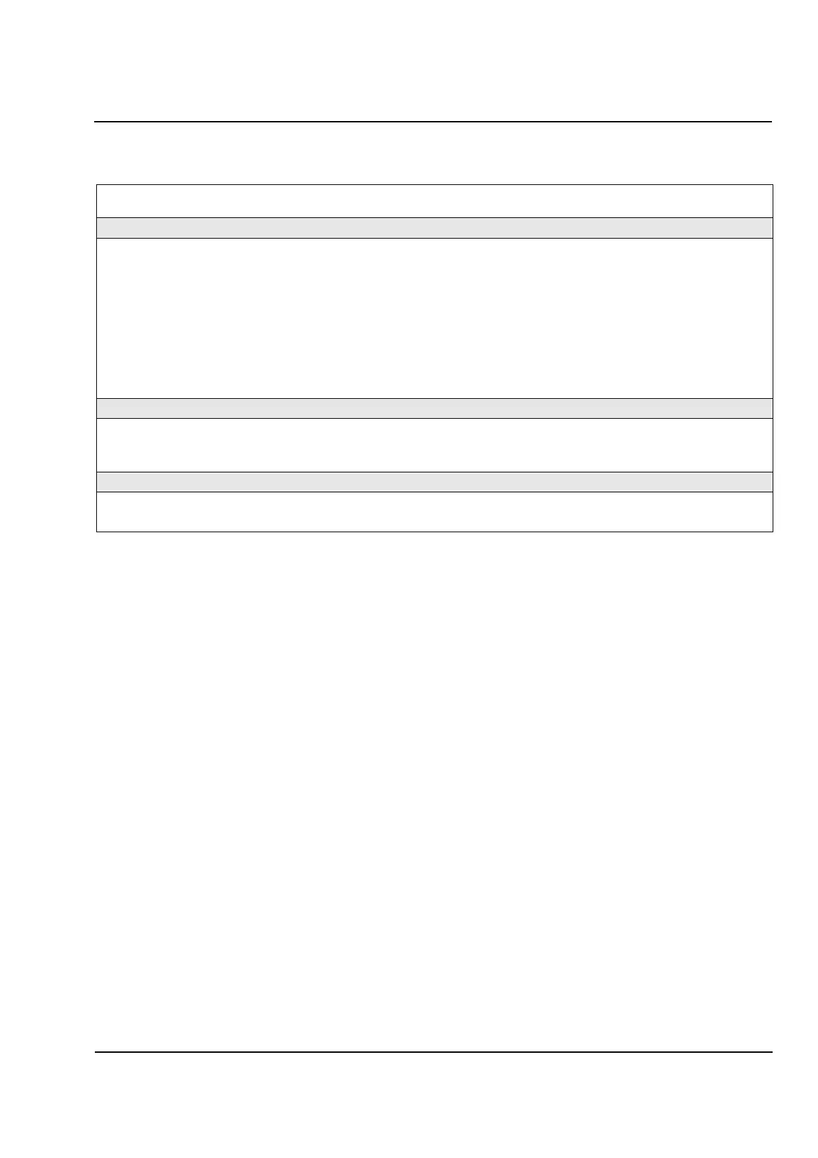
2.13 Tank Leakage Protection (64T)
Table 2.10
Specifications for Tank Leakage Protection (64T)
2.14 Service, Storage, and Transport Conditions
The relay is designed for use in industrial and
electric-utility environments. It should be installed in
standard relay rooms and compartments so that with
proper installation electromagnetic compatibility
(EMC) is ensured. The relay is not designed for use in
residential, commercial or light-industrial environment.
The following should also be heeded:
All contactors and relays which operate in the
same cubicle or on the same relay panel as
the digital protection equipment should, as a
rule, be fitted with suitable spike quenching
elements.
All external connection leads in substations from 100
kV upwards should be screened with a screen capable
of carrying power currents and grounded at both
sides. No special measures are normally necessary
for substations of lower voltages.
Do not withdraw or insert relay module into its housing
when under voltage.
When the relay module is withdrawn from its housing,
some internal components are vulnerable to damage
by electrostatic discharges; therefore, handling
standards for electrostatically endangered
components should be observed. The relay module is
not electrostatically endangered when plugged in.
The removable front panel of the relay must be
securely in place when the relay is in service (to
ensure a complete and secure electrical connection
between the relay module and the terminal blocks on
the rear of the relay housing).
Specifications for service, storage, and transport
conditions are listed in Table 2.11, following this
paragraph.
Measuring Principle Measurement of the leakage current from the isolated tank to
ground.
Settings
Ground leakage current pickup (dependent on connection) 10mA to 1000mA (1mA steps) Sensitive CT B
0.10 to 10.00 In (0.01In steps) Insensitive CTA
Trip Delay Time 0.00 to 60.00 s or ∞ for no trip (0.01 s steps)
Drop
-
off Delay Time 0.00 to 60.00 s (0.01 s steps)
Drop
-
off Ratio 0.25 to 0.95 (0.01 steps)
Events that can control signal contacts, trip contacts, or
LEDs
Change in operational status; pickup, dropout, trip, and reset
events, start of time delay before trip. All events are logged, as
are the amplitude of the ground current and the phase
-
angle
difference at the time of a trip.
Inherent Operating Times
Pick
-
up Time at 2 times setting value (without parallel
operation of other protection functions) (approx.)
25 to 35 ms (60 ms at 16
2/3
Hz)
Drop
-
off Time (approx.) 35 ms (100 ms at 16
2/3
Hz)
Operating Tolerances (with default settings)
Pickup Current ±5% of setting value
Delay Times ±1% of setting value or 10 ms, whichever is greater
 Loading...


