17
Installation and Servicing
7UT51 v3
192 PRIM-2330C
17.10 Changing the Rated Voltage of the Binary
-
Signal Inputs
A binary-signal input is actuated by applying a control
voltage across its two terminals. When delivered from
the factory, the voltage required to actuate the binary
input is the same as the relay’s DC supply power
voltage, which is specified when the relay is ordered. If
appropriate, the actuating-voltage for each
binary-signal input can be independently changed to a
different voltage. The change requires a hardware
modification.
1. Remove the module(s) from the relay case as
described in Section XREF.
2. If the last two characters of the relay’s serial
number are JH or alphabetically earlier, use a
soldering iron, connect or disconnect the wire
jumpers as shown in Figure 17.17.
or
If the last two characters of the relay’s serial
number are KK or alphabetically later, position
the plug jumpers and shown in Figure 17.18
and Figure 17.19.
3. Return the module(s) to the relay case, as
described in Section XREF.
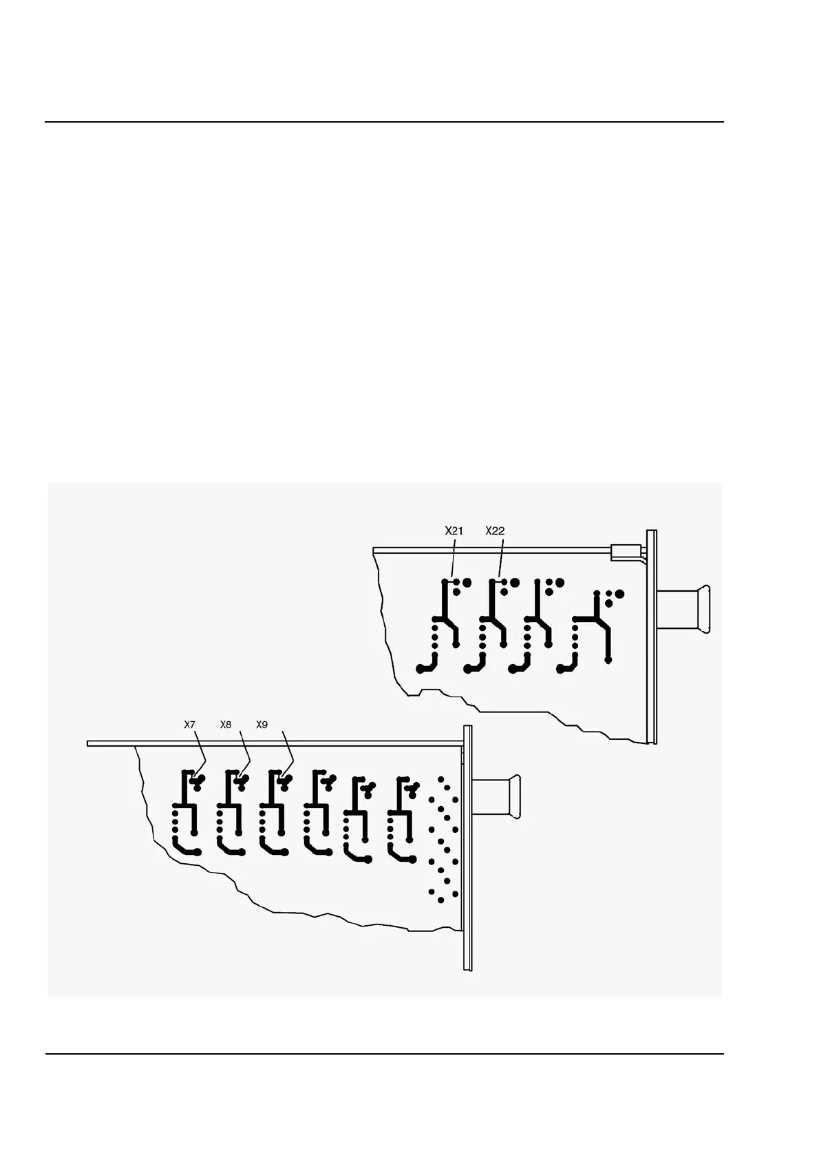
Figure 17.17
Locations of Jumpers for Setting Rated Voltage of Binary
-
Signal Inputs (for Production Series /JH or Earlier).
For a rated voltage of 24/48/60V, CONNECT the wire jumper corresponding to the binary
-
signal input.
For a rated voltage of 110/125/220/250V, DISCONNECT the wire jumper corresponding to the binary
-
signal input.
Binary
-
Signal Input 1: Wire Jumper X21
Binary
-
Signal Input 2: Wire Jumper X22
Main Module (7UT512 and 7UT513):
Binary
-
Signal Input 3: Wire Jumper X7
Binary
-
Signal Input 4: Wire Jumper X8
Binary
-
Signal Input 5: Wire Jumper X9
Auxiliary Module (7UT513 only):
 Loading...


