7 Ground Differential Protection (87N)
7UT51 v3
92 PRIM-2330C
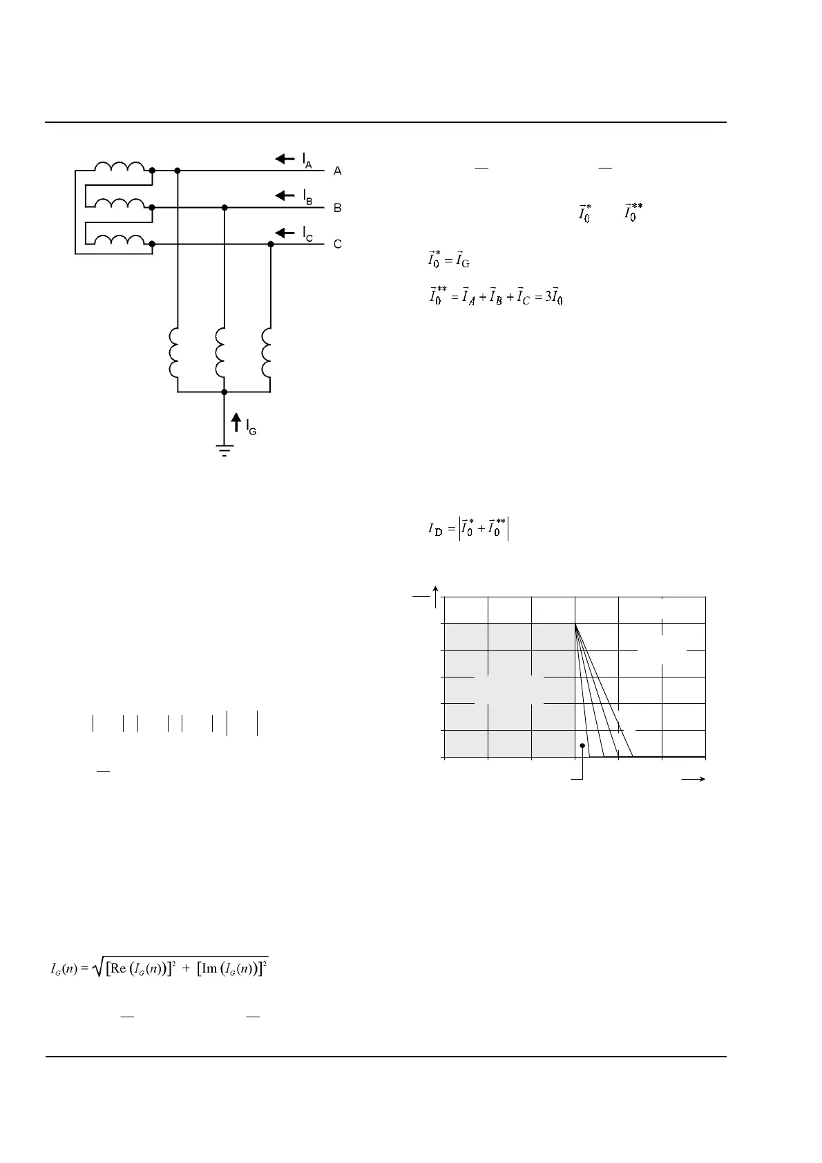
Figure 7.3
Ground Differential Protection of a Delta
Winding with a Shunt Reactor
7.1 Calculated Quantities
The restraining current,
I
R
, is the scalar sum of the
separate amplitudes of the measured phase and
ground currents. It is a measure of the total amount of
current flowing through the transformer, regardless of
whether the currents are balanced. It is calculated
according to equation 7.1 and equation 7.2:
(7.1)
(7.2)
where
N
is the number of samples taken during each
power system cycle, while
i
A
(
k
),
i
B
(
k
),
i
C
(
k
), and
i
G
(
k
)
are the sampled and normalized values of the phase
and ground currents.
The fundamental vector of the ground current,
I
G
, is
calculated using Fourier analysis:
(7.3)
(7.4)
(7.5)
Two calculated current vectors, and , are the major
components of the algorithm:
(7.6)
(7.7)
Both quantities are calculated using the
Fourier-analysis algorithm described in equation 7.3,
equation 7.4, and equation 7.5.
The differential current,
I
D
, is by definition the
amplitude of the vector-difference of the measured
ground current and the calculated zero sequence
current. By convention, any current flowing into the
protected equipment is considered to have a positive
magnitude; so
I
D
is calculated using the following
equation:
(7.8)
Figure 7.4
Trip Area for I*o/Io**=1
)()()()()(
kikikikiki
G
CBAR
+++=
∑
−
=
−=
1
0
)(
1
)(
N
k
RR
kni
N
nI
()
)2cos()(
2
)(Re
1
0
N
k
kni
N
nI
N
k
GG
π
∑
−
=
−=
()
)2sin()(
2
)(Im
1
0
N
k
kni
N
nI
N
k
GG
π
∑
−
=
−=
0.0
0.2
0.4
0.6
0.8
1.0
1.2
0 30 60 90 120 150 180
1/
**
0
*
0
=
II
4.06
2.04
1.37
*
0
I
I
OP
ϕ
(degrees)
k
0
= 1.03
CLASSICAL
TRIP AREA
EXTENDED TRIP AREA
BLOCK
AREA
 Loading...


