18
Field Testing and Commissioning
7UT51 v3
208 PRIM-2330C
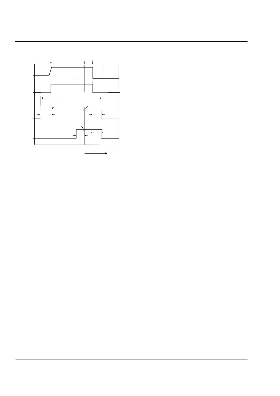
Figure 18.7
Waveform Capture
18.9 Installation of 7UT51
Relay in Existing Circuit
The installation of the Siemens 7UT51 relay in an
energized circuit can be perform without disturbing the
existing system.
The following must be completed before the relay can
be fully functional in the circuit:
• Settings applied
• Acceptance / Installation Tested (out of circuit)
Once all of the necessary and applicable testing has
been performed on the relay, the relay can be
prepared for installation and testing.
Ensure that trip circuits are disconnected from the
relay trip contacts and are left open-circuited. Do not
connect any of the relay outputs to any external
breaker failure devices.
If test switches are available, place all related switches
in the test position.
Read and record magnitude and phase angle readings
in all leads and windings.
Perform Section 18.8 on page 206
Perform a manual Waveform capture through
Address Block 4900 and verify the primary and
secondary waveforms using WinDIGSI and DIGRA.
Verify all measurable quantities (inputs) through the
relay.
Compare the known current values with the displayed
test currents. If deviations occur that cannot be
explained by tolerances, recheck connections and test
arrangement and repeat.
When assessing the currents, note that the differential
and stabilizing values are referred to the rated current
of the protected object.
18.9.1 Output Connections
With test switches in the test position, proceed with
making all trip and signal output connections.
Note:
Since the relay is installed in an energized
circuit, operational checks of each output
cannot be performed; however, all outputs from
the relay are checked prior to installation and
all control circuitry is checked upon installation
or subsequent outages.
A complete functional
check for all trip and signal outputs should be
performed during the next available outage.
18.10 Testing for In
-
Service
Setting Changes
Perform only the tests in the procedure that are
applicable to the change.
** - Time point where decision to store waveform data is made.
Shown for each of the three trigger options.
PRETRIG
POSTTRIG
< MAX LENGTH
PRETRIG
POSTTRIG
Waveform
Capture
with Trip
**TRG PU/ SAVE TRIP
**TRIG WITH TRIP
** TRIG WITH PICK UP
-100ms
0ms
100ms 100ms 200ms
300ms
Current
Protection
Pickup
Trip Drop-Out
Time
Waveform
Capture
with Pickup
 Loading...


