7UT51 v3
Bus Differential Protection (87B)
6
PRIM-2330C 85
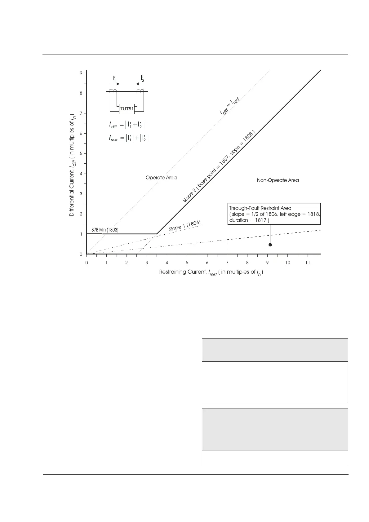
Figure 6.3
Differential Protection Characteristic for a Bus
6.5 Through
-
Fault Restraint
CT saturation caused by a high-current internal fault
(or by long system time constants) affects the
differential current,
I
diff
, and the restraining current,
I
rest
, about equally; however, a high-current
through-fault can cause considerable differential
current due to unequal CT saturation at the different
CT measuring locations. For this situation, the
differential protection function can be configured to
achieve the desired tripping restraint.
A high-current external fault is characterized by an
initial rise in the restraining current that is much more
rapid than the initial rise in the differential current. If
the operating point moves quickly (within 0.5 cycle)
into the through-fault-detection area shown in
Figure 6.3, the 87B function will restrained for a
configurable duration. The restraint will be released if,
for two complete cycles, the ratio of the differential
current to the restraining current is less than 0.9 (that
is, the operating point moves up to within 90% of the
I
diff
=I
rest
line on Figure 6.3), which would indicate an
internal fault is evolving during the external fault.
1817 T-SAT-BLK
Maximum duration of through
-
fault CT
-
saturation restraint
of the 87B function.
Range: 2
–
250 cycles, or
∞
(until drop
-
off of pickup)
Default: 8 cycles
The timer starts when the operating point enters the
through
-
fault restraint area (see Figure 6.3). Enter
∞
for the
restraint to continue until dropout of the differential
protection pickup.
1818 SAT-RESTR.
Minimum restraint current required to activate through
-
fault
CT
-
saturation restraint. This value sets the left edge of the
through
-
fault restraint area shown in Figure 6.3. The top of
the area is a line passing through the origin whose slope is
one
-
half the slope of Slope 1 (Address 1806).
Range: 5.00
–
15.00
I
n
Default: 7.00
I
n
 Loading...


