7UT51 v3
Operation Using the Front Panel Controls
14
PRIM-2330C 139
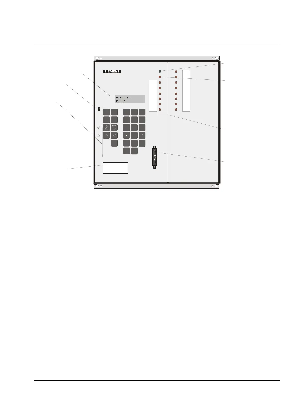
Figure 14.2
7UT513 Front Panel
14.1.5 LED Indicators
The 7UT512 relay has eight LEDs, six of which can be
configured by the user. The 7UT513 relay has 16
LEDs, 14 of which can be configured by the user.
Each configurable LED can indicate up to ten events
of conditions chosen from a long list. See Section 13.4
on page 128 of this manual for more information.
The LEDs that cannot be changed for either relay
model are as follows:
Power
– Lights up GREEN to indicate the relay
powered on and is working properly. Normally, this
indicator will remain on. It will be off if the On/Off
switch is in the “
Off
” position or if power to the relay is
interrupted. It also will be off if any of the internal
failure monitoring functions detect a device failure.
Blocked
– Lights up RED to indicate that the relay has
detected an internal problem and has blocked itself
from operation. This LED also will light briefly during
initial power-up and after the protected system setting,
system frequency setting, or input/output function
assignments are changed and saved.
The remaining LEDs (1 through 6 for the 7UT512 or 1
through 14 for the 7UT513) will light up RED to
indicate that the annunciation assigned to this LED
indicator during the configuration process has
occurred. These indicators will remain on until reset,
and the relay will retain this data even if power is lost.
Whether or not the indications are retained in the
nonvolatile memory is a configuration option. If the
indications are not retained, they will be reset when
the fault condition is removed. If they are retained,
they can be reset locally by the Target Reset key on
the front panel, through a serial port, through a binary
input. If another fault occurs before the LEDs are
reset, the relay will automatically reset the LEDs and
light the LEDs appropriate for the new fault.
To reset the LEDs, press
Target Reset
on the front
panel, or go to
Address 8201 RESET LED?
and
press
Yes
.
19
7
210
8
311
412
513
614
7
8
9
4
56
0
1
23
F
No
Yes
Enter
Data Port
Back
Space
∞
Pass
word
Direct
Addr
Ta r ge t
Reset
Ta r ge t
Reset
On
Off
7UT
Numerical Differential Protection
Transformer / Gen erator/ Motor
Event
Power
Blocked
+ -
Power LED
Indicate s relay is in service
(Green)
Blocked LED
Indicates relay protection
function is blocked
(Red)
Programmable LEDs (Red)
RS-232
Communications
Interface
Alphanumeric Display
On/O ff Switch
Keypad
Nameplate
Includes model number
 Loading...


